Caterpillar Cat 312C and 312C L Excavator (Prefix FDS) Service Repair Manual Instant Download
Please open the website below to get the complete manualnn//

Download Presentation

Please find below an Image/Link to download the presentation.
The content on the website is provided AS IS for your information and personal use only. It may not be sold, licensed, or shared on other websites without obtaining consent from the author. Download presentation by click this link. If you encounter any issues during the download, it is possible that the publisher has removed the file from their server.
E N D
Presentation Transcript
Service Repair Manual Models 312C and312C L Excavator
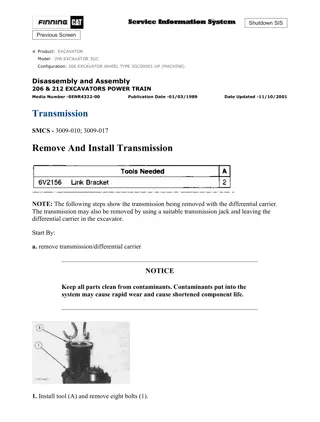
w 1/3(W) Shutdown SIS Previous Screen Product: EXCAVATOR Model: 312C EXCAVATOR FDS Configuration: 312C & 312C L Excavators FDS00301-UP (MACHINE) POWERED BY 3064 Engine Disassembly and Assembly 3064 and 3066 Engines for Caterpillar Built Machines Media Number -SENR5553-10 Publication Date -01/05/2012 Date Updated -15/05/2012 i01615420 Gear Group (Front) - Install - Idler Gear Only SMCS - 1206-012 Installation Procedure Table 1 Required Tools Tool Part Number Part Description Qty A 1P-0510 Driver Group 1 NOTICE Keep all parts clean from contaminants. Contaminants may cause rapid wear and shortened component life. https://127.0.0.1/sisweb/sisweb/techdoc/techdoc_print_page.jsp?returnurl=/sisweb/sisw... 2020/5/12
w 2/3(W) Illustration 1 g00611570 1. Use Tool (A) to install a new bushing (4) (not shown), if the bushing was removed. Illustration 2 g00611572 2. Install idler shaft (5) onto the cylinder block. Note: When the idler shaft is installed, ensure that the oil hole of the shaft is up. If necessary, cool the idler shaft to 0 C (32 F) before installation. The temperature of the idler shaft is lowered in order to ease the installation of the idler shaft. Illustration 3 g00611569 Note: Ensure that the marks on the timing gears are in alignment. Align the fuel injection drive gear with the "33" mark with the "3" mark on idler gear. Make an alignment of the "2" mark on the camshaft gear with the "22" mark on the idler gear. Align the "1" mark on the crankshaft gear with the "11" mark on the idler gear. The No. 1 cylinder is at the top center position when these marks are in alignment. 3. Install idler gear (3) onto the idler shaft. https://127.0.0.1/sisweb/sisweb/techdoc/techdoc_print_page.jsp?returnurl=/sisweb/sisw... 2020/5/12
https://www.ebooklibonline.com Hello dear friend! Thank you very much for reading. Enter the link into your browser. The full manual is available for immediate download. https://www.ebooklibonline.com
w 3/3(W) Illustration 4 g00611568 4. Install thrust plate (2) onto the idler shaft. 5. Install the washer and idler gear bolt (1) onto thrust plate (2). Tighten idler gear bolt (1) to a torque of 34 5 N m (25 4 lb ft). Note: For more information, refer to Specifications, "Gear Group (Front)". Note: See the following list for the installation of the other gears in the front gear group. In order to install the camshaft gear, refer to Disassembly and Assembly, "Camshaft - Install". In order to install the fuel injection pump gear, refer to Disassembly and Assembly, "Fuel Injection Pump - Install". In order to install the gear from the engine oil pump, refer to Disassembly and Assembly, "Engine Oil Pump - Install". In order to install the crankshaft front gear, refer to Disassembly and Assembly, "Crankshaft Gear - Remove and Install". End By: Install the front housing. Refer to Disassembly and Assembly, "Housing (Front) - Install". Copyright 1993 - 2020 Caterpillar Inc. Tue May 12 10:24:53 UTC+0800 2020 All Rights Reserved. Private Network For SIS Licensees. https://127.0.0.1/sisweb/sisweb/techdoc/techdoc_print_page.jsp?returnurl=/sisweb/sisw... 2020/5/12
w 1/4(W) Shutdown SIS Previous Screen Product: EXCAVATOR Model: 312C EXCAVATOR FDS Configuration: 312C & 312C L Excavators FDS00301-UP (MACHINE) POWERED BY 3064 Engine Disassembly and Assembly 3064 and 3066 Engines for Caterpillar Built Machines Media Number -SENR5553-10 Publication Date -01/05/2012 Date Updated -15/05/2012 i01615434 Housing (Front) - Remove SMCS - 1151-011 Removal Procedure Table 1 Required Tools Tool Part Number Part Description Qty A 1P-0510 Driver Group 1 Start By: A. Remove the alternator. Refer to Disassembly and Assembly, "Alternator - Remove and Install". B. Remove the water pump. Refer to Disassembly and Assembly, "Water Pump - Remove". C. Remove the crankshaft pulley. Refer to Disassembly and Assembly, "Crankshaft Pulley - Remove and Install". D. Remove the fuel injection pump. Refer to Disassembly and Assembly, "Fuel Injection Pump - Remove". NOTICE Keep all parts clean from contaminants. Contaminants may cause rapid wear and shortened component life. NOTICE https://127.0.0.1/sisweb/sisweb/techdoc/techdoc_print_page.jsp?returnurl=/sisweb/sisw... 2020/5/12
w 2/4(W) Care must be taken to ensure that fluids are contained during performance of inspection, maintenance, testing, adjusting and repair of the product. Be prepared to collect the fluid with suitable containers before opening any compartment or disassembling any component containing fluids. Refer to Special Publication, NENG2500, "Caterpillar Tools and Shop Products Guide" for tools and supplies suitable to collect and contain fluids on Caterpillar products. Dispose of all fluids according to local regulations and mandates. Illustration 1 g00605981 1. Loosen hose clamp (1) that secures hose (2) to the front housing. 2. Disconnect hose (2) from the front housing. Illustration 2 g00605985 https://127.0.0.1/sisweb/sisweb/techdoc/techdoc_print_page.jsp?returnurl=/sisweb/sisw... 2020/5/12
w 3/4(W) 3. Remove bolts (3) and the washers that hold front housing (4) to the plate and the cylinder block. 4. Remove six bolts (5) (not shown) and the washers that mount the front housing (4) to the oil pan. Illustration 3 g00606002 5. Remove two bolts (6) and the washers that mount the front housing (4) to the front plate (8) and the cylinder block. 6. Use two technicians to remove the front housing from the cylinder block and the front plate. The weight of the front housing is 20 kg (45 lb). Note: Check the condition of the gasket (7) (not shown) for the engine oil pan. If the gasket is damaged, it may be necessary to replace the gasket. Refer to Disassembly and Assembly, "Engine Oil Pan - Remove and Install" for replacement of the gasket for the engine oil pan. https://127.0.0.1/sisweb/sisweb/techdoc/techdoc_print_page.jsp?returnurl=/sisweb/sisw... 2020/5/12
w 4/4(W) Illustration 4 g00606022 7. Remove old gasket material (9) from the mating surface of front housing (4) and the timing gear plate. Note: Check the condition of crankshaft front seal (10) (not shown). If the crankshaft front seal is worn or damaged, use a new part for replacement. 8. Use Tool (A) to remove the crankshaft front seal (10) (not shown) from the front housing (4), if necessary. 9. Check the teeth of the timing gears for the following items: wear, nicks, chips and uneven contact. Check the keyway for wear or damage. Copyright 1993 - 2020 Caterpillar Inc. Tue May 12 10:25:48 UTC+0800 2020 All Rights Reserved. Private Network For SIS Licensees. https://127.0.0.1/sisweb/sisweb/techdoc/techdoc_print_page.jsp?returnurl=/sisweb/sisw... 2020/5/12
w 1/4(W) Shutdown SIS Previous Screen Product: EXCAVATOR Model: 312C EXCAVATOR FDS Configuration: 312C & 312C L Excavators FDS00301-UP (MACHINE) POWERED BY 3064 Engine Disassembly and Assembly 3064 and 3066 Engines for Caterpillar Built Machines Media Number -SENR5553-10 Publication Date -01/05/2012 Date Updated -15/05/2012 i01615441 Housing (Front) - Install SMCS - 1151-012 Installation Procedure Table 1 Required Tools Tool Part Number Part Description Qty A 1P-0510 Driver Group 1 NOTICE Keep all parts clean from contaminants. Contaminants may cause rapid wear and shortened component life. https://127.0.0.1/sisweb/sisweb/techdoc/techdoc_print_page.jsp?returnurl=/sisweb/sisw... 2020/5/12
w 2/4(W) Illustration 1 g00836619 Alignment marks for timing gears 1. Check the alignment of the timing gears. Note: Ensure that the marks on the timing gears are in alignment. Align the fuel injection drive gear with the "33" mark with the "3" mark on idler gear. Make an alignment of the "2" mark on the camshaft gear with the "22" mark on the idler gear. Align the "1" mark on the crankshaft gear with the "11" mark on the idler gear. The No. 1 cylinder is at the top center position when the timing marks are in alignment. Note: When the marks are aligned, the piston in No. 1 cylinder is at the top center position on the compression stroke. Note: Refer to Specifications, "Gear Group (Front)" for specifications on the assembly of the timing gears. Illustration 2 g00606022 https://127.0.0.1/sisweb/sisweb/techdoc/techdoc_print_page.jsp?returnurl=/sisweb/sisw... 2020/5/12
w 3/4(W) 2. Ensure that the old gasket material (9) is removed from the mating surface of front housing (4) and the timing gear plate. Install a new gasket. 3. If the crankshaft front seal (10) (not shown) was removed, use Tool (A) to install a new crankshaft front seal. Illustration 3 g00606002 4. Before installation of the front housing, check the gasket (7) (not shown) for the oil pan for damage. Replace the gasket, if necessary. Refer to Disassembly and Assembly, "Engine Oil Pan - Remove and Install" for replacement of the gasket for the engine oil pan. 5. Use two technicians to install the front housing onto the front plate and the cylinder block. The weight of the front housing is 20 kg (45 lb). 6. Install two bolts (6) in order to fasten front housing (4) onto the cylinder block and the front plate (8) . https://127.0.0.1/sisweb/sisweb/techdoc/techdoc_print_page.jsp?returnurl=/sisweb/sisw... 2020/5/12
w 4/4(W) Illustration 4 g00605985 7. Install the washers and six bolts (5) (not shown) in order to secure front housing (4) onto engine oil pan. 8. Install bolts (3) and washers that secure the front housing (4) to the front plate and the cylinder block. Illustration 5 g00605981 9. Connect hose (2) to the front housing. 10. Install the hose clamp (1) in order to secure the hose to the front housing. End By: a. Install the fuel injection pump. Refer to Disassembly and Assembly, "Fuel Injection Pump - Install". b. Install the crankshaft pulley. Refer to Disassembly and Assembly, "Crankshaft Pulley - Remove and Install". c. Install the water pump. Refer to Disassembly and Assembly, "Water Pump - Install". d. Install the alternator. Refer to Disassembly and Assembly, "Alternator - Remove and Install". Copyright 1993 - 2020 Caterpillar Inc. Tue May 12 10:26:44 UTC+0800 2020 All Rights Reserved. Private Network For SIS Licensees. https://127.0.0.1/sisweb/sisweb/techdoc/techdoc_print_page.jsp?returnurl=/sisweb/sisw... 2020/5/12
w 1/2(W) Shutdown SIS Previous Screen Product: EXCAVATOR Model: 312C EXCAVATOR FDS Configuration: 312C & 312C L Excavators FDS00301-UP (MACHINE) POWERED BY 3064 Engine Disassembly and Assembly 3064 and 3066 Engines for Caterpillar Built Machines Media Number -SENR5553-10 Publication Date -01/05/2012 Date Updated -15/05/2012 i01615486 Front Plate - Remove SMCS - 1163-011 Removal Procedure Start By: a. Remove the idler gear. Refer to Disassembly and Assembly, "Gear Group (Front) - Remove". b. Remove the camshaft. Refer to Disassembly and Assembly, "Camshaft - Remove". c. Remove the fuel injection pump. Refer to Disassembly and Assembly, "Fuel Injection Pump - Remove". NOTICE Keep all parts clean from contaminants. Contaminants may cause rapid wear and shortened component life. https://127.0.0.1/sisweb/sisweb/techdoc/techdoc_print_page.jsp?returnurl=/sisweb/sisw... 2020/5/12
w 2/2(W) Illustration 1 g00611711 1. Remove one bolt (1) and the washer from the front plate (2). 2. Remove front plate (2) from the engine. 3. Remove gasket (3) (not shown) from the engine or from the front plate (2). Note: Ensure that all mating surfaces are clear of old gaskets. Note: Check the cylinder block for the following conditions: scale buildup, corrosion and other damage. Copyright 1993 - 2020 Caterpillar Inc. Tue May 12 10:27:40 UTC+0800 2020 All Rights Reserved. Private Network For SIS Licensees. https://127.0.0.1/sisweb/sisweb/techdoc/techdoc_print_page.jsp?returnurl=/sisweb/sisw... 2020/5/12
w 1/2(W) Shutdown SIS Previous Screen Product: EXCAVATOR Model: 312C EXCAVATOR FDS Configuration: 312C & 312C L Excavators FDS00301-UP (MACHINE) POWERED BY 3064 Engine Disassembly and Assembly 3064 and 3066 Engines for Caterpillar Built Machines Media Number -SENR5553-10 Publication Date -01/05/2012 Date Updated -15/05/2012 i01576831 Front Plate - Install SMCS - 1163-012 Installation Procedure NOTICE Keep all parts clean from contaminants. Contaminants may cause rapid wear and shortened component life. Illustration 1 g00611711 1. Place gasket (3) (not shown) in position on the engine. Note: Ensure that all mating surfaces are clear of old gaskets. 2. Place front plate (2) in position on the engine. https://127.0.0.1/sisweb/sisweb/techdoc/techdoc_print_page.jsp?returnurl=/sisweb/sisw... 2020/5/12
w 2/2(W) 3. Install one bolt (1) and the washer in order to secure front plate (2) to the engine. Tighten the bolt to a torque of 35 5 N m (26 4 lb ft). End By: a. Install the fuel injection pump. Refer to Disassembly and Assembly, "Fuel Injection Pump - Install". b. Install the camshaft. Refer to Disassembly and Assembly, "Camshaft - Install". c. Install the idler gear. Refer to Disassembly and Assembly, "Gear Group (Front) - Install". Copyright 1993 - 2020 Caterpillar Inc. Tue May 12 10:28:35 UTC+0800 2020 All Rights Reserved. Private Network For SIS Licensees. https://127.0.0.1/sisweb/sisweb/techdoc/techdoc_print_page.jsp?returnurl=/sisweb/sisw... 2020/5/12
w 1/3(W) Shutdown SIS Previous Screen Product: EXCAVATOR Model: 312C EXCAVATOR FDS Configuration: 312C & 312C L Excavators FDS00301-UP (MACHINE) POWERED BY 3064 Engine Disassembly and Assembly 3064 and 3066 Engines for Caterpillar Built Machines Media Number -SENR5553-10 Publication Date -01/05/2012 Date Updated -15/05/2012 i01568835 Crankcase Breather - Remove and Install SMCS - 1317-010 Removal Procedure NOTICE Keep all parts clean from contaminants. Contaminants may cause rapid wear and shortened component life. NOTICE Care must be taken to ensure that fluids are contained during performance of inspection, maintenance, testing, adjusting and repair of the product. Be prepared to collect the fluid with suitable containers before opening any compartment or disassembling any component containing fluids. Refer to Special Publication, NENG2500, "Caterpillar Tools and Shop Products Guide" for tools and supplies suitable to collect and contain fluids on Caterpillar products. Dispose of all fluids according to local regulations and mandates. https://127.0.0.1/sisweb/sisweb/techdoc/techdoc_print_page.jsp?returnurl=/sisweb/sisw... 2020/5/12
w 2/3(W) Illustration 1 g00814599 1. Loosen hose clamps (2) on hose (1). Remove the hose from the breather assembly (3) . 2. Remove breather assembly (3) from valve mechanism cover (4) . Installation NOTICE Keep all parts clean from contaminants. Contaminants may cause rapid wear and shortened component life. Illustration 2 g00814599 1. Install new breather assembly (3). 2. Install hose (1) on the breather assembly (3) and tighten the hose clamp (2) . Tue May 12 10:29:31 UTC+0800 2020 https://127.0.0.1/sisweb/sisweb/techdoc/techdoc_print_page.jsp?returnurl=/sisweb/sisw... 2020/5/12
w 1/3(W) Shutdown SIS Previous Screen Product: EXCAVATOR Model: 312C EXCAVATOR FDS Configuration: 312C & 312C L Excavators FDS00301-UP (MACHINE) POWERED BY 3064 Engine Disassembly and Assembly 3064 and 3066 Engines for Caterpillar Built Machines Media Number -SENR5553-10 Publication Date -01/05/2012 Date Updated -15/05/2012 i01567534 Valve Mechanism Cover - Remove and Install SMCS - 1107-010 Removal Procedure NOTICE Keep all parts clean from contaminants. Contaminants may cause rapid wear and shortened component life. Illustration 1 g00814243 1. Loosen hose clamp (2) and remove hose (1) from the air inlet manifold (3) and the turbocharger (7) . 2. Loosen hose clamps (4) and disconnect hose (5) from the breather (6) . https://127.0.0.1/sisweb/sisweb/techdoc/techdoc_print_page.jsp?returnurl=/sisweb/sisw... 2020/5/12
w 2/3(W) 3. Remove bolts (8) and the washers from valve mechanism cover (9) . Note: The 3064 Engine has four bolts and washers while the 3066 Engine has six bolts and washers. Earlier models of the 3064 and 3066 Engines used acorn nuts and washers in place of bolts. 4. Remove valve mechanism cover (9) . Note: The 3064 Engine has one valve mechanism cover while the 3066 Engine has two valve mechanism covers. Installation Procedure NOTICE Keep all parts clean from contaminants. Contaminants may cause rapid wear and shortened component life. Illustration 2 g00814243 1. Check the condition of the gasket on valve mechanism cover (9). If the gasket is worn or damaged, use a new part for replacement. 2. Install valve mechanism cover (9). Install the washers and bolts (8) . Note: The 3064 Engine has four bolts and washers while the 3066 Engine has six bolts and washers. Note: The 3064 Engine has one valve mechanism cover while the 3066 Engine has two valve mechanism covers. Earlier models of the 3064 and 3066 Engines used acorn nuts and washers in place of bolts. 3. Torque bolts (8) to 15 3 N m (11 2 lb ft). https://127.0.0.1/sisweb/sisweb/techdoc/techdoc_print_page.jsp?returnurl=/sisweb/sisw... 2020/5/12
w 3/3(W) 4. Install hose (5) onto the breather (6). Tighten two hose clamps (4) that secure the hose. 5. Install hose (1) and tighten hose clamp (2) that secures the hose to the air inlet manifold (3) and to the turbocharger (7) . Copyright 1993 - 2020 Caterpillar Inc. Tue May 12 10:30:27 UTC+0800 2020 All Rights Reserved. Private Network For SIS Licensees. https://127.0.0.1/sisweb/sisweb/techdoc/techdoc_print_page.jsp?returnurl=/sisweb/sisw... 2020/5/12
w 1/2(W) Shutdown SIS Previous Screen Product: EXCAVATOR Model: 312C EXCAVATOR FDS Configuration: 312C & 312C L Excavators FDS00301-UP (MACHINE) POWERED BY 3064 Engine Disassembly and Assembly 3064 and 3066 Engines for Caterpillar Built Machines Media Number -SENR5553-10 Publication Date -01/05/2012 Date Updated -15/05/2012 i01147997 Rocker Shaft and Pushrod - Remove SMCS - 1102-011; 1208-011 Removal Procedure Start By: A. Remove the valve mechanism cover. Refer to Disassembly and Assembly, "Valve Mechanism Cover - Remove and Install". NOTICE Keep all parts clean from contaminants. Contaminants may cause rapid wear and shortened component life. Illustration 1 g00609267 https://127.0.0.1/sisweb/sisweb/techdoc/techdoc_print_page.jsp?returnurl=/sisweb/sisw... 2020/5/12
w 2/2(W) 1. Loosen adjusting screws (1) on each the rocker arms about one rotation. 2. Loosen six short bolts (2) and the washers on the rocker shaft brackets. 3. Loosen six long bolts (3) for the rocker shaft bracket. 4. Remove six bolts (3) from the rocker shaft brackets. 5. Remove six short bolts (2) and the washers from the rocker shaft brackets. 6. Remove the rocker shaft assembly (4) from the cylinder head. Note: Perform Steps 1 through 6 for the other rocker shaft assembly on the 3066 Engine. Note: Check the contact surface of the adjusting screw (1) for wear from the pushrods and check for threads that are stripped. Illustration 2 g00609287 7. Put identification marks on pushrods (5) in order to identify the location of the pushrods in the engine. Remove six pushrods (5) from each head assembly (6) ( 3066 Engine) or remove eight pushrods (5) from head assembly (6) ( 3064 Engine). Note: Check pushrods for worn ends and check for distortion. If necessary, replace any pushrods that are worn or distorted. 8. Remove valve caps (7) from the valve stem. This will prevent the valve cap from becoming lost. Note: Check the contact surface of the valve caps for wear and check for oil passages that are clogged. Copyright 1993 - 2020 Caterpillar Inc. Tue May 12 10:31:23 UTC+0800 2020 All Rights Reserved. Private Network For SIS Licensees. https://127.0.0.1/sisweb/sisweb/techdoc/techdoc_print_page.jsp?returnurl=/sisweb/sisw... 2020/5/12
w 1/3(W) Shutdown SIS Previous Screen Product: EXCAVATOR Model: 312C EXCAVATOR FDS Configuration: 312C & 312C L Excavators FDS00301-UP (MACHINE) POWERED BY 3064 Engine Disassembly and Assembly 3064 and 3066 Engines for Caterpillar Built Machines Media Number -SENR5553-10 Publication Date -01/05/2012 Date Updated -15/05/2012 i01615500 Rocker Shaft - Disassemble SMCS - 1102-015 Disassembly Procedure Table 1 Required Tools Tool Part Number Part Description Qty A 1P-0510 Driver Group 1 Start By: A. Remove the rocker shaft and pushrods. Refer to Disassembly and Assembly, "Rocker Shaft and Pushrod - Remove". NOTICE Keep all parts clean from contaminants. Contaminants may cause rapid wear and shortened component life. 1. Mark the location and the position of each component for later assembly. https://127.0.0.1/sisweb/sisweb/techdoc/techdoc_print_page.jsp?returnurl=/sisweb/sisw... 2020/5/12
w 2/3(W) Illustration 1 g00609488 Illustration 2 g00609491 2. Remove bolt (1) and oil supply tube (2) from the end of shaft assembly (5) . 3. Remove clip (3) and remove spacer (4) from shaft assembly (5) . Note: Check the spacer for wear. Replace the spacer, if necessary. 4. Slide components to the left and off the end of shaft assembly (5) . 5. The shaft assembly includes the following components: Bolt (1) Oil tube (2) Clip (3) Spacer (4) Shaft assembly (5) Rocker arm (6) Bushing (7) https://127.0.0.1/sisweb/sisweb/techdoc/techdoc_print_page.jsp?returnurl=/sisweb/sisw... 2020/5/12
Suggest: If the above button click is invalid. Please download this document first, and then click the above link to download the complete manual. Thank you so much for reading
w 3/3(W) Rocker shaft bracket (8) Spring (9) 6. Remove clip (3) and remove spacer (4) from the other end of shaft assembly (5) . Note: Check the spacer for wear. Replace the spacer, if necessary. Illustration 3 g00609490 7. Inspect bushing (7) for wear or damage. Use Tool (A) to remove the bushing from rocker arm (6), if necessary. Refer to Specifications, "Rocker Shaft" for more information. Copyright 1993 - 2020 Caterpillar Inc. Tue May 12 10:32:18 UTC+0800 2020 All Rights Reserved. Private Network For SIS Licensees. https://127.0.0.1/sisweb/sisweb/techdoc/techdoc_print_page.jsp?returnurl=/sisweb/sisw... 2020/5/12
https://www.ebooklibonline.com Hello dear friend! Thank you very much for reading. Enter the link into your browser. The full manual is available for immediate download. https://www.ebooklibonline.com