CASE SR175 Tier 4B Alpha Series Skid Steer Loader Service Repair Manual Instant Download
Please open the website below to get the complete manualnn//
Download Presentation

Please find below an Image/Link to download the presentation.
The content on the website is provided AS IS for your information and personal use only. It may not be sold, licensed, or shared on other websites without obtaining consent from the author. Download presentation by click this link. If you encounter any issues during the download, it is possible that the publisher has removed the file from their server.
E N D
Presentation Transcript
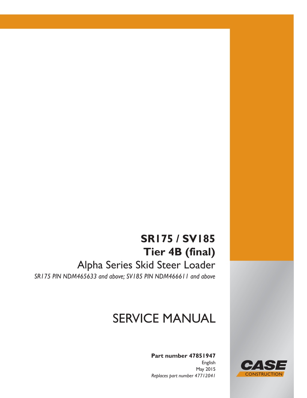
SR175 / SV185 Tier 4B (final) Alpha Series Skid Steer Loader SR175 PIN NDM465633 and above; SV185 PIN NDM466611 and above SERVICE MANUAL Part number 47851947 Printed in U.S.A. 2015 CNH Industrial America LLC. All Rights Reserved. Case is a trademark registered in the United States and many other countries, owned by or licensed to CNH Industrial N.V., English May 2015 Replaces part number 47712041 its subsidiaries or affiliates.
SERVICE MANUAL SR175TIER4B (FINAL) [NDM465633-] SV185TIER4B (FINAL) [NDM466611-] 47851947 15/05/2015 EN
Link Product / Engine Product Market Product Engine SR175TIER4BFinal[NDM465633-] North America N4LDI-TA-50SL SV185TIER4B Final [NDM466611-] North America N4LDI-TA-45SL 47851947 15/05/2015
https://www.ebooklibonline.com Hello dear friend! Thank you very much for reading. Enter the link into your browser. The full manual is available for immediate download. https://www.ebooklibonline.com
Contents INTRODUCTION Engine....................................................................................... 10 [10.001] Engine and crankcase ............................................................. 10.1 [10.400] Engine cooling system ............................................................. 10.2 [10.414] Fan and drive ...................................................................... 10.3 Power coupling........................................................................... 19 [19.121] Pump-drive assembly .............................................................. 19.1 Front axle system ....................................................................... 25 [25.450] Chain drive system................................................................. 25.1 Rear axle system........................................................................ 27 [27.650] Chain drive system................................................................. 27.1 Hydrostatic drive......................................................................... 29 [29.202] Hydrostatic transmission ........................................................... 29.1 [29.134] Two-speed assembly............................................................... 29.2 [29.200] Mechanical control ................................................................. 29.3 [29.218] Pump and motor components...................................................... 29.4 Brakes and controls .................................................................... 33 [33.110] Parking brake or parking lock ...................................................... 33.1 Hydraulic systems....................................................................... 35 [35.000] Hydraulic systems.................................................................. 35.1 [35.104] Fixed displacement pump.......................................................... 35.2 [35.300] Reservoir, cooler, and filters........................................................ 35.3 [35.359] Main control valve.................................................................. 35.4 [35.525] Auxiliary hydraulic valves and lines ................................................ 35.5 [35.600] High flow hydraulics................................................................ 35.6 [35.701] Front loader arm hydraulic system................................................. 35.7 47851947 15/05/2015
[35.724] Front loader hydraulic system control.............................................. 35.8 [35.734] Tool quick coupler hydraulic system ............................................... 35.9 Frames and ballasting................................................................. 39 [39.140] Ballasts and supports .............................................................. 39.1 Wheels...................................................................................... 44 [44.511] Front wheels........................................................................ 44.1 [44.520] Rear wheels........................................................................ 44.2 Cab climate control..................................................................... 50 [50.100] Heating............................................................................. 50.1 [50.200] Air conditioning..................................................................... 50.2 Electrical systems....................................................................... 55 [55.000] Electrical system ................................................................... 55.1 [55.011] Fuel tank system ................................................................... 55.2 [55.012] Engine cooling system ............................................................. 55.3 [55.014] Engine intake and exhaust system................................................. 55.4 [55.019] Hydrostatic drive control system ................................................... 55.5 [55.031] Parking brake electrical system.................................................... 55.6 [55.036] Hydraulic system control ........................................................... 55.7 [55.050] Heating, Ventilation, and Air-Conditioning (HVAC) control system................. 55.8 [55.100] Harnesses and connectors......................................................... 55.9 [55.302] Battery............................................................................ 55.10 [55.408] Warning indicators, alarms, and instruments .................................... 55.11 [55.512] Cab controls...................................................................... 55.12 [55.640] Electronic modules............................................................... 55.13 [55.DTC] FAULT CODES.................................................................. 55.14 Front loader and bucket............................................................... 82 [82.100] Arm................................................................................. 82.1 [82.300] Bucket.............................................................................. 82.2 47851947 15/05/2015
Platform, cab, bodywork, and decals............................................. 90 [90.150] Cab................................................................................. 90.1 [90.154] Cab doors and hatches ............................................................ 90.2 47851947 15/05/2015
INTRODUCTION 47851947 15/05/2015 1
Contents INTRODUCTION Foreword - Important notice regarding equipment servicing (*) ................................3 Safety rules (*) ..................................................................................4 Safety rules - Personal safety (*) ...............................................................5 Safety rules - Ecology and the environment (*) .................................................6 Safety rules (*) ..................................................................................7 Torque - Minimum tightening torques for normal assembly (*) .................................8 Torque - Standard torque data for hydraulics (*) .............................................. 13 Basic instructions - Shop and assembly (*) ................................................... 15 Hydraulic contamination Contamination (*) ................................................. 17 General specification - Left-hand instrument cluster (*) ...................................... 18 General specification - Electronic Instrument Cluster (EIC) (*) ............................... 20 General specification - Advanced Instrument Cluster (AIC) (*) ............................... 25 General specification - Biodiesel fuels (*) ..................................................... 30 Capacities (*) ................................................................................. 33 Product identification .......................................................................... 34 Product identification - Machine orientation (*) ............................................... 36 (*) See content for specific models 47851947 15/05/2015 2
INTRODUCTION Foreword - Important notice regarding equipment servicing SR175 SV185 All repair and maintenance work listed in this manual must be carried out only by qualified dealership personnel, strictly complying with the instructions given, and using, whenever possible, the special tools. Anyone who performs repair and maintenance operations without complying with the procedures provided herein shall be responsible for any subsequent damages. The manufacturer and all the organizations of its distribution chain, including - without limitation - national, regional, or local dealers, reject any responsibility for damages caused by parts and/or components not approved by the manu- facturer, including those used for the servicing or repair of the product manufactured or marketed by the manufacturer. In any case, no warranty is given or attributed on the product manufactured or marketed by the manufacturer in case of damages caused by parts and/or components not approved by the manufacturer. The manufacturer reserves the right to make improvements in design and changes in specifications at any time without notice and without incurring any obligation to install them on units previously sold. Specifications, descriptions, and illustrative material herein are as accurate as known at time of publication but are subject to change without notice. In case of questions, refer to your CASE CONSTRUCTION Sales and Service Networks. 47851947 15/05/2015 3
INTRODUCTION Safety rules SR175 SV185 Personal safety This is the safety alert symbol. It is used to alert you to potential personal injury hazards. Obey all safety messages that follow this symbol to avoid possible death or injury. Throughout this manual you will find the signal words DANGER, WARNING, and CAUTION followed by special in- structions. These precautions are intended for the personal safety of you and those working with you. Read and understand all the safety messages in this manual before you operate or service the machine. DANGER indicates a hazardous situation that, if not avoided, will result in death or serious injury. WARNING indicates a hazardous situation that, if not avoided, could result in death or serious injury. CAUTION indicates a hazardous situation that, if not avoided, could result in minor or moderate injury. FAILURE TO FOLLOW DANGER, WARNING, AND CAUTION MESSAGES COULD RESULT IN DEATH OR SERIOUS INJURY. Machine safety NOTICE: Notice indicates a situation that, if not avoided, could result in machine or property damage. Throughout this manual you will find the signal word Notice followed by special instructions to prevent machine or property damage. The word Notice is used to address practices not related to personal safety. Information NOTE: Note indicates additional information that clarifies steps, procedures, or other information in this manual. Throughout this manual you will find the word Note followed by additional information about a step, procedure, or other information in the manual. The word Note is not intended to address personal safety or property damage. 47851947 15/05/2015 4
INTRODUCTION Safety rules - Personal safety SR175 SV185 Carefully study these precautions, and those included in the external attachment operators manual, and insist that they be followed by those working with and for you. 1. Thoroughly read and understand this manual and the attachment Operator s Manual before operating this or any other equipment. 2. Be sure all people and pets are clear of the machine before starting. Sound the horn, if equipped, three times before starting engine. 3. Only the operator should be on the machine when in operation. Never allow anyone to climb on to the machine while it is in motion. If the machine is equipped with an Instructors Seat, this must only be used for training purposes. Passengers must not be allowed to use the Instructors Seat. 4. Keep all shields in place. Never work around the machine or any of the attachments while wearing loose clothing that might catch on moving parts. 5. Observe the following precautions whenever lubricating the machine or making adjustments. Disengage all clutching levers or switches. Lower the attachment, if equipped, to the ground or raise the attachment completely and engage the cylinder safety locks. Completing these actions will prevent the attachment from lowering unexpectedly. Engage the parking brake. Shut off the engine and remove the key. Wait for all machine movement to stop before leaving the operators platform. 6. Always keep the machine in gear while travelling downhill. 7. The machine should always be equipped with sufficient front or rear axle weight for safe operation. 8. Under some field conditions, more weight may be required at the front or rear axle for adequate stability. This is especially important when operating in hilly conditions or/when using heavy attachments. 9. Always lower the attachment, shut off the engine, set the parking brake, engage the transmission gears, remove the key and wait for all machine movement to stop before leaving the operators platform. 10. If the attachment or machine should become obstructed or plugged; set the parking brake, shut off the engine and remove the key, engage the transmission gears, wait for all machine or attachment motion to come to a stop, before leaving the operators platform to removing the obstruction or plug. 11. Never disconnect or make any adjustments to the hydraulic system unless the machine and/or the attachment is lowered to the ground or the safety lock(s) is in the engaged position. 12. Use of the flashing lights is highly recommended when operating on a public road. 13. When transporting on a road or highway, use accessory lights and devices for adequate warning to the opera- tors of other vehicles. In this regard, check local government regulations. Various safety lights and devices are available from your CASE CONSTRUCTION dealer. 14. Practice safety 365 days a year. 15. Keep all your equipment in safe operating condition. 16. Keep all guards and safety devices in place. 17. Always set the parking brake, shut off the engine and remove the key, engage the transmission gears, wait for all machine or attachment motion to come to a stop, before leaving the operators platform to service the machine and attachment. 18. Remember: A careful operator is the best insurance against an accident. 19. Extreme care should be taken in keeping hands and clothing away from moving parts. 47851947 15/05/2015 5
INTRODUCTION Safety rules - Ecology and the environment SR175 SV185 Soil, air, and water quality is important for all industries and life in general. When legislation does not yet rule the treatment of some of the substances that advanced technology requires, sound judgment should govern the use and disposal of products of a chemical and petrochemical nature. Familiarize yourself with the relative legislation applicable to your country, and make sure that you understand this legislation. Where no legislation exists, obtain information from suppliers of oils, filters, batteries, fuels, anti-freeze, cleaning agents, etc., with regard to the effect of these substances on man and nature and how to safely store, use, and dispose of these substances. Helpful hints Avoid the use of cans or other inappropriate pressurized fuel delivery systems to fill tanks. Such delivery systems may cause considerable spillage. In general, avoid skin contact with all fuels, oils, acids, solvents, etc. Most of these products contain substances that may be harmful to your health. Modern oils contain additives. Do not burn contaminated fuels and or waste oils in ordinary heating systems. Avoid spillage when you drain fluids such as used engine coolant mixtures, engine oil, hydraulic fluid, brake fluid, etc. Do not mix drained brake fluids or fuels with lubricants. Store all drained fluids safely until you can dispose of the fluids in a proper way that complies with all local legislation and available resources. Do not allow coolant mixtures to get into the soil. Collect and dispose of coolant mixtures properly. The air-conditioning system contains gases that should not be released into the atmosphere. Consult an air-condi- tioning specialist or use a special extractor to recharge the system properly. Repair any leaks or defects in the engine cooling system or hydraulic system immediately. Do not increase the pressure in a pressurized circuit as this may lead to a component failure. Protect hoses during welding. Penetrating weld splatter may burn a hole or weaken hoses, allowing the loss of oils, coolant, etc. Battery recycling Batteries and electric accumulators contain several substances that can have a harmful effect on the environment if the batteries are not properly recycled after use. Improper disposal of batteries can contaminate the soil, groundwater, and waterways. CASE CONSTRUCTION strongly recommends that you return all used batteries to a CASE CONSTRUCTION dealer, who will dispose of the used batteries or recycle the used batteries properly. In some countries, this is a legal requirement. Mandatory battery recycling NOTE: The following requirements are mandatory in Brazil. Batteries are made of lead plates and a sulfuric acid solution. Because batteries contain heavy metals such as lead, CONAMA Resolution 401/2008 requires you to return all used batteries to the battery dealer when you replace any batteries. Do not dispose of batteries in your household garbage. Points of sale are obliged to: Accept the return of your used batteries Store the returned batteries in a suitable location Send the returned batteries to the battery manufacturer for recycling 47851947 15/05/2015 6
SERVICE MANUAL Engine SR175 TIER 4B Final [NDM465633 - ] SV185 TIER 4 [NDM466611 - ] 47851947 15/05/2015 10
Contents Engine - 10 [10.001] Engine and crankcase ............................................................... 10.1 [10.400] Engine cooling system ............................................................... 10.2 [10.414] Fan and drive ........................................................................ 10.3 47851947 15/05/2015 10
Engine - 10 Engine and crankcase - 001 SR175 TIER 4B Final [NDM465633 - ] SV185 TIER 4 [NDM466611 - ] 47851947 15/05/2015 10.1 [10.001] / 1
Contents Engine - 10 Engine and crankcase - 001 SERVICE Engine Drain fluid . . . . . . . . . . . . . . . . . . . . . . . . . . . . . . . . . . . . . . . . . . . . . . . . . . . . . . . . . . . . . . . . . . . . . . . . . . . . . . . . . 3 Remove (*) . . . . . . . . . . . . . . . . . . . . . . . . . . . . . . . . . . . . . . . . . . . . . . . . . . . . . . . . . . . . . . . . . . . . . . . . . . . . . . . . 4 Install (*) . . . . . . . . . . . . . . . . . . . . . . . . . . . . . . . . . . . . . . . . . . . . . . . . . . . . . . . . . . . . . . . . . . . . . . . . . . . . . . . . . 13 (*) See content for specific models 47851947 15/05/2015 10.1 [10.001] / 2
Engine - Engine and crankcase Engine - Drain fluid 1. Remove the access cover at the rear, lower left of the machine, exposing the engine oil drain hose and re- mote oil filter. 2. Remove the drain plug to drain the oil. 3. When the oil has completely drained, reinstall the drain plug and torque to 68 - 82 N m (50 - 61 lb ft). 1 63109370 47851947 15/05/2015 10.1 [10.001] / 3
Engine - Engine and crankcase Engine - Remove NA NA SR175 TIER 4B Final [NDM465633 - ] SV185 TIER 4 [NDM466611 - ] WARNING Avoid injury! Always do the following before lubricating, maintaining, or servicing the machine. 1. Disengage all drives. 2. Engage parking brake. 3. Lower all attachments to the ground, or raise and engage all safety locks. 4. Shut off engine. 5. Remove key from key switch. 6. Switch off battery key, if installed. 7. Wait for all machine movement to stop. Failure to comply could result in death or serious injury. W0047A WARNING Fire hazard! When handling diesel fuel, observe the following precautions: 1. Do not smoke. 2. Never fill the tank when the engine is running. 3. Wipe up spilled fuel immediately. Failure to comply could result in death or serious injury. W0099A DANGER Heavy objects! Lift and handle all heavy components using lifting equipment with adequate capacity. Always support units or parts with suitable slings or hooks. Make sure the work area is clear of all bystanders. Failure to comply will result in death or serious injury. D0076A Prior operation: Tilt the Roll Over Protection Structure (ROPS). Prior operation: Disconnect the battery. See Battery - Disconnect (55.302). Prior operation: Drain the coolant. See Prior operation: Drain the oil. Prior operation: Recover the A/C refrigerant (if applicable). See Air conditioning - Discharging (50.200) 1. Remove the engine hood strut from the side by gently prying the retaining clip just enough to release the strut. 2. Disconnect the A/C lines (if applicable). 3. Disconnect the lights and disconnect the harness from the hood. 4. Remove the engine hood mounting hardware from left- hand and right-hand side of the engine hood. 5. Remove the engine hood . 47851947 15/05/2015 10.1 [10.001] / 4
Engine - Engine and crankcase 6. Remove the engine cover (1). 1 RAIL13SSL0128AA 7. Remove the air filter assembly (1) and hoses. 2 RAIL13SSL0145AA 8. Remove the fuel filter assembly (1) and plug the hoses. 9. Remove the bracket (2) for the air filter assembly. 10. Remove the oil fill tube (3). 11. Disconnect the mount (4) for the oil dip stick from the cooling package bracket. 12. For vertical lift machines, remove the cotter pin on the lock pin link for the left boom. Unbolt the boom lock bellcrank (5) and place it away from the engine area. 3 RAIL13SSL0144AA 47851947 15/05/2015 10.1 [10.001] / 5
Engine - Engine and crankcase 13. Remove the bracket (1) for the coolant overflow bottle. 4 RAIL13SSL0143AA 14. Remove the air cooler (1). 5 RAIL13SSL0142AA 15. Remove the coolant overflow bottle. 6 RAIL13SSL0141AA 47851947 15/05/2015 10.1 [10.001] / 6
Engine - Engine and crankcase 16. Remove the radiator (1). 7 RAIL13SSL0140AA 17. Loosen the alternator mounting bolt (3) and the mounting bolt (2) for the adjustment bolt (1). 18. Remove the tension from the belt by turning the ad- justment screw (1) on the alternator. 8 RAIL13SSL0139AA 19. Remove the engine fan assembly. 9 RAIL13SSL0138AA 47851947 15/05/2015 10.1 [10.001] / 7
Engine - Engine and crankcase 20. Remove the cooling package bracket assembly (1). 10 RAIL13SSL0604AA 21. Disconnect the positive battery cable (1) on the alter- nator. 22. Disconnect the electrical connector (2) on the alterna- tor. 23. Disconnect the starter ignition wire (3). 24. Disconnectthepositivebatterycable(4)onthestarter. 11 RAIL13SSL0130AA 25. If applicable, disconnect the supply and return hoses for the heater core. NOTE: The supply hose is located on the left-hand side of the engine and the return hose is located on the right-hand side of the engine. 26. Disconnect and cap the lines (1) for the remote, oil filter housing. 12 RAIL13SSL0129AA 47851947 15/05/2015 10.1 [10.001] / 8
Engine - Engine and crankcase 27. Disconnect and cap the fuel feed line (1) and the fuel return line (2). 13 RAIL13SSL0132AA 28. Remove the access plate (1) for the engine oil pan. 14 RAPH12SSL0233AA 29. Disconnect the remote drain line (1) from the engine oil pan. 15 RAIL13SSL0147AA 47851947 15/05/2015 10.1 [10.001] / 9
Engine - Engine and crankcase 30. Disconnect the following sensors: pressure sensor (1) pre-oxidation temperature sensor (2) post-oxidation temperature sensor (3) 16 RAIL13SSL0137AA 31. Unbolt the pressure sensor from the cross member. 17 RAIL13SSL0136AA 32. Disconnect both exhaust pipes (2). 33. Remove the mounting bolts (1), and carefully remove the filter/muffler assembly. 18 RAIL13SSL0146AA 47851947 15/05/2015 10.1 [10.001] / 10
Engine - Engine and crankcase 34. Disconnect the joystick linkage (1) from the hydro- static pump assembly. 19 RAIL13SSL0126AA 35. Support the hydrostatic pump assembly with a suit- able lifting device. 20 RAIL13SSL0131AA 36. Disconnect the ground wire (1). 37. Unplug the engine harness (2). 38. Unbolt the engine harness (3) from the bell housing. 39. Carefully remove the return spring assembly (4). 21 RAIL13SSL0135AA 47851947 15/05/2015 10.1 [10.001] / 11
Engine - Engine and crankcase 40. Remove the rear engine mount bolts (1). 22 RAIL13SSL0134AA 41. Remove the front engine mount bolts (1). 23 931001933 42. Unbolt the hydrostatic pump assembly (1), and disen- gage the pump assembly (1) from the bell housing. 24 RAIL13SSL0133AA 43. Apply suitable lifting equipment to the engine, and carefully lift the engine out the machine. 47851947 15/05/2015 10.1 [10.001] / 12
Engine - Engine and crankcase Engine - Install NA NA SR175 TIER 4B Final [NDM465633 - ] SV185 TIER 4 [NDM466611 - ] 1. Carefully lower the engine into the machine. 2. Engage the pump assembly into the bell housing. Ap- ply LOCTITE 243 to the bolts (1). Torque the bolts (1) to 87 - 117 N m (64 - 86 lb ft). 1 RAIL13SSL0133AA 3. Install the front engine mount bolts (1). Apply LOCTITE 243 to the bolts (1). Torque the bolts (1) to 163 - 176 N m (120 - 130 lb ft). 2 931001933 4. Install the rear engine mount bolts (1). Apply LOCTITE 243 to the bolts (1). Torque the bolts (1) to 163 - 176 N m (120 - 130 lb ft). 3 RAIL13SSL0134AA 47851947 15/05/2015 10.1 [10.001] / 13
Suggest: If the above button click is invalid. Please download this document first, and then click the above link to download the complete manual. Thank you so much for reading
Engine - Engine and crankcase 5. Carefully install the return spring assembly (4). 6. Connect the ground wire (1). 7. Bolt the engine harness (3) to the bell housing. 8. Connect the engine harness (2). 4 RAIL13SSL0135AA 9. Remove the lifting device (1) from the hydrostatic pump assembly. 5 RAIL13SSL0131AA 10. Connect the joystick linkage (1) to the hydrostatic pump assembly. 6 RAIL13SSL0126AA 47851947 15/05/2015 10.1 [10.001] / 14
https://www.ebooklibonline.com Hello dear friend! Thank you very much for reading. Enter the link into your browser. The full manual is available for immediate download. https://www.ebooklibonline.com


