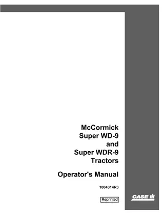
Case IH McCormick Super W-6 Tractor Operator’s Manual Instant Download (Publication No.1004277R2)
Please open the website below to get the complete manualnn//
Download Presentation

Please find below an Image/Link to download the presentation.
The content on the website is provided AS IS for your information and personal use only. It may not be sold, licensed, or shared on other websites without obtaining consent from the author. Download presentation by click this link. If you encounter any issues during the download, it is possible that the publisher has removed the file from their server.
E N D
Presentation Transcript
McCormick Super W-6 Tractor Operator's Manual 1004277R2
6 THIS SAFETY ALERT SYMBOL INDICATES IMPORTANT SAFETY MESSAGES IN THIS MANUAL. WHEN YOU SEE THIS SYMBOL, , CAREFULL Y READ THE MESSAGE THAT FOLLOWS AND BE ALERT TO THE POSSIBILITY OF PERSONAL INJURY OR DEA TH. M171B If Safety Decals on this machine use the words Danger, Warning or Caution, which are defined as follows: DANGER: Indicates an immediate hazardous situation which if not avoided, will result in death or serious injury. The color associated with Danger is RED. WARNING: Indicates an potentially hazardous situation which if not avoided, will result in serious injury. The color associated with Warning is ORANGE. CAUTION: Indicates an potentially hazardous situation which if not avoided, may result in minor or moderate injury. It may also be used to alert against unsafe practices. The color associated with Caution is YELLOW. If Safety Decals on this machine are ISO two panel Pictorial, decals are defined as follows: The first panel indicates the nature of the hazard. The second panel indicates the appropriate avoidance of the hazard. Background color is YELLOW."" 6 WARNING IMPROPER OPERATION OF THIS MACHINE CAN CAUSE INJURY OR DEATH. BEFORE USING THIS MACHINE, MAKE CERTAIN THAT EVERY OPERATOR: Prohibition symbols such as \:::I X and 8 if used, are RED. Is instructed in safe and proper use of the machine. Reads and understands the Manual(s) pertaining to the machine. Reads and understands ALL Safety Decals on the machine. Clears the area of other persons. Learns and practices safe use of machine controls in a safe, clear area before operating this machine on a job site. It is your responsibility to observe pertinent laws and regulations and follow Case Corporation instructions on machine operation and maintenance. Bur 0-00000 2001 Case Corporation issued November, 1994 CASE and IH are registered trademarks of Case Corporation
McCORMICK Super W-6 Tractor
https://www.ebooklibonline.com Hello dear friend! Thank you very much for reading. Enter the link into your browser. The full manual is available for immediate download. https://www.ebooklibonline.com
TO THE OWNER ., .1"'119 u tnterufloMllfa.n!l.lu t:rac:faI' .. 'fOIII' aft' poww ~ you lutft parduaead a prod:act of .. of .. wodcl' ......... ~ 111m you ... oblIm m:. Ids macIIiDe .......... ad nper10r pel61.'._ it iI < I 'JOIII ... deItN a 1uve ..... of panouJ ",.cIo:a m:. t I . of fana., I.' W. W to 9i'N. It iI o.tam tJaat ~ ~ Y-.noftractor ... ~ with ~ ~ ~ a d a d a l o o a f l l d probIe;ru in .. fWd ..... ban orablMdw6 in ttafJiltltdao ad ~ dace all ...... ad relaem.ext.lIlndlt Izdo 'fOIII' tractor. 1M a : - . l _ o f ~ b e u i a dept_We iapitil:m, --lutelJwMel ad the ....... oil ad fuel ....... __ of ...... mr. tMt gift JOU t:rac:faI' II .... poww to do all JOU POWW joba with ~ 1 t 1 l l l \ operated, ad DlilltaiMd, Ids t:rac:faI' ... NIpOIIad to ...., ..... We <1 __ 'JOIII make .. it ad 9i'N 'JOIII ....u.w. .. vb .. .,... to CICIIIle. .... to PlIO' ) p . " ~ o r a U : t W " i:m:IHlla ~ &peed ad ecaUIIII,. Pmped;y adjuI:ad, II it .. p:6:IJ of ImamaIoMl If.uwMr o-PlIIJ to impI:ote .. pmd.ucIB wheuvw it it pcaiWe ad pmdic:aJ to do c. w:-. nuMt .. Ii9ht to make cU,.. or add -PI"' .... at uy IsH wit'bcNt ~ to make n.dl.,.. em tracton a .., ~ d ~ . All ... Iull ........... ""' ............... II II ......, ............................................. .. ........ 6 ......... lin .... 1kC JIIII ....... .. .................... '1 .......... ......
CONTENTS Description INTRODUCTION Delivery report (to be filled in when tractor is delivered) General .. .. .... .. Serial numbers. engine and tractor. , . . ... , . . . . . At front 2 eLivery report DESCRIPTION Before starting your new tractor .. Instruments and controls .... Preparing your tractor for each day I s work V iews of the tractor. . . . . . . . . . . . . 7. 8 4to6 8. 9 .3 OPERATING YOUR TRACTOR Driving the tractor , . , ...... . Operating a gasoline engine . . . . . , . . Operating a distillate engine ...... Operating a distillate engine on gasoline Operating a kerot.cne engine ..... Operating the belt pulley ...... Operatins the Hydraulic Remote Control Ol-erating the power take-off . . . . 16. 17 10, 11 12 to 14 15 15 18 20 19 LUBRICATION Engine and chassis lubricant specifications General engine lubri.c:ation . . . . . . . . . Greasing tne front wheels ........ . Lubrication guide . . . . . . . . . . . . . Lubricating oil and grease specifications. Oil filter ... .............. 30 21 32 Z3 to 29 31 21. 22 MAINTENANCE Adjus ting the drawbar . Air cleaning system. Battery ignition unit Brakes .. ..... Carburetor. . . . . . Clutch ........ Cold weather precautions Cooling system . Cranking motor . . . . Fuel strainer . .... Generator . . .. .... Hydraulic Remote Control system Magneto (tractors so equipped) Periodic inspections . .... Pneumatic 'iires . . . . . . . . . .. Spark pluss and cables . . . . . . . . . . . . Starting and lighting equipment (tractors with battery ignition) Starting and IiShting equipment (tractors with magneto) Starting engines that have been in storage Storage battery Storing and housing your tractor Trouble shootins ... .. Valve clearance adjustment. . . . . Wheels . " ., . . ,. .. . . "" Wiring diagrams (starting and lighting) 67 40, 41 42 to 45 64, 65 34. 35 66 36, 37 37 to 39 53, 58, 59 34 51 to 53, 57. 58 n 46 to 49 33 69 to 71 41. 42 49 to 55 56 to 59 78 59 to 61 78 73 to 77 63 68 54 to 56 . . ;$ " "" .. .. SPECIAL EQUIPMENT 79 to 9l SPECIFICATIONS .. 93. 94 95, 96 COMPREHENSIVE INDEX 1
INTRODUCTION Assembled in this book are operating and maintenance instructions for the Super W -0. This material has been prepared in detail in the hope that it will help you to better under- stand the correct care and efficient operation of your tractor. If you should need information not given in this manual. Or require the services of a trained mechanic, get in touch with the Inter- national Harvester dealer in your locality. Dealers are kept informed on the latest meth- ods of servicing tractors. They carry stocks of 1H parts. and are backed in every case by the full facilities of a nearby International Harvester District Office. Throughout this manual the use of the terms LEFT. RIGHT. FRONT, and REAR must be understood to avoid confusion when follow- ing instructions. LEFT and RIGHT indicate the left and right sides of the tractor when fac- ing forward in the driver I s seat. to FRONT indicates the radiator end of the tractor, and REAR the drawbar end of the tractor. See Illust. 2. ~ e f e r e n c e lHust. 2 housing. See Illust. 2A. is preceded by the prefix SW -6. The engine serial number is stamped on the right side of the engine crankcase above the crankcase breather. See IUust. 2B. ber is preceded by the prefix C-Z64. which in .. dicates that it is a carbureted engine with a Z64-cubic-inch piston displacement. The serial number The illustrations in this manual are num- bered to correspond with the pages on which they appeal': for example; lllusts. 6. 6A ana 6B are on DOte 6. This serial num- When in need of parts, always specify the tractor and engine serial numbers. The tractor serial number is stamped on a name plate attached on the left side of the clutch For ready reference we suggest that you write these serial numbers in the spaces pro- vided on the Delivery Report. InUIt. 2A Ilhst. 28 Location of tractor seria1 number. Location of engine serial number.
DESCRIPTION I,just. 3 - Right front view. II hlst. 3A .. Left front view. 3
DESCRIPTION INSTRUMENTS AND CONTROLS A variety of speelal equipment is available for use with the Super -'6. The in.tructions for operating and maintaining the special equipment have been in- cluded in the In.tructions for operating and maintaining the tractor. Disregard the instruction. for soeela! eQuiDMl'lt not on your tractor. IIlnt ... Location of instruments and controls. To assist in making a sharp turn, operate the pedals individually. depressing the pedal on the side toward which the turn is to be made. Brake Pedals These pedals are used to stop the tractor. to hold the tractor in a stationary position, or to assist in makin, sharp turns as outlined be- low: The brake pedal latch (Illusts and 17) is und to latch both brake pedals together. causing the brakes to operate simultaneously. CAUTI o.n Always latch the brake pedals together when driving the tractor in high gear (5th speed). To latch the pedals together, en- gage the latch (located in back of left pedal. Illust. 4) in the slot in back of the right pedal. When brake pedals are not latched together. the latch should rest in the slot in back of the len brake pedal. To stop the tractor, depress both pedals at the same time. Before drivin, the tractor in bigh ,ear. always latch the pedals to,ether. To hold the tractor in a stationary posi- tion. latch the pedals to,ethe r. de- press and lock them in this depressed position by pullin, out the brake pedal lock control rod.
DESCRIPTION The brake pedal lock (IlZusts. 4 and 17) is used to lock the brake pedals in the de- pressed position which prevents the tractor from moving. Lighting Switch The switch has three positions. "0" - off position; HD" .. dim lights; and "B" - bright lights. Clutch Pedal Ammeter This pedal. when depressed all the way, disengages the engine from the transmission. This instrument indicates the charging rate of the generator or the diSCharge rate of the batte ry. If it shows diSCharge continu" ously, investigate the cause to avoid com- pletely discharging the battery and possible damage to the generator. Refer to D<J,es 49 to 61 for additional information on electrical equipment. Choke Rod The choke rod makes it possible to regu- late the carburetor choke from the driver I s seat. Pulling out on the choke rod closes the carburetor choke for starting the engine; push- ing it back in opens the choke. Oil Pressure Indicator Engine Speed Control Lever This lever controls the speed of the en .. gine and. when set in a given position, will maintain a uniform engine speed even though the engine load may vary. The rated or maximum full load governed speed is 1.450 r.p.m.; maximum idle speed is approximately 1,600 r.p.m.; minimum idle speed (hand throttle) is 400 to 450 r.p.m. with the engine speed control lever fully retarded. Never operate the engine at more than the regular governed speed, Excessive speeds are harmful. 111ult. S Oil pressure indicator, snowing needle in correct oPerating position. The governor is set at the factory and should require no adjustment. Consult your International Harvester dealer if the governor does not function properly. This indicator (Illusts. 4 ana 5) shows whether lubricating oil is circulating through the engine. The indicator needle should reg- ister in the white area when the engine is run- ning at speeds approximately 100 r.p.m. above slow idle speeds (Illust. 51. If it is not in the white area, stop tne engine immediately and investigate the cause of the oil pressure failure. If you are unable to find the cause, be sure to consult your International Harvel> te r dealer before operating the engine. Ignition SWitch Button This button closes and opens the electrical circuit for operating and stopping the engine. Pull the button out f ~ to stop the engine. operating and push it in CAUTION: On tractors with battery ignition, when the engine is not operating or the engine has stalled and the operator leaves the tractor, the ignition switch button must be pushed all the way in, So' that the switch is in the "OFF" position, to prevent battery discharge. Radiator Shutter Control Crank The control crank opens and closes the radiator shutter, controlling the engine tern perature. Turn the crank counterclockwise to close the shutter and clockwise to open tnt' shutter. Starting Switch Control Rod To start the engine, adjust the choke rod and pull out on the starting switch control rod as explained on pa4e 11. .OlE: Tractors with gasoline engines a rtt not regularly equipped with this feature. 5
DESCRIPTION Gearshift Lever Fourth speed forward Illust. SA Heat indicator in correct operating position wben operating on distillate or kerosene. First speed forward Manifold Heat Control Lever 111ust. S Geershift positions. This lever is used to select the various gear ratios in the transmission. There are five forward speeds and one reverse speed. See IZ lust. 6. ll1ust. 68 MOTE: The fifth speed is locked out when steel wheels are used; for further instructions refer to pale 17. Heat control valve set in hot position (distI1- late or kerosene engines only). This control lever (lllu.st. 6fJ) is used only on distillate or kerosene engines. For normal operation. set the lever in the top notch II MOTI! position. If the distillate or kerosene engine is to be operated on gasoline, set the control lever in the bottom notch "COLDn position, and remove the mani old shield. To change positions. loosen the lock nut on the lever and move the lever to the de- sired position. For complete instructions re- fer to ;:;a,es 13 to 15. Power Take-Off ShUter Rod The shifter rod is used to engage or dis- engage the power take-of{. Refer to ;:;ate 19 for operating instructions. Heat Indicator This instrument (Illusts. 4 and 6AJ indi- cates when the liquid in the cooling system is at the proper temperature for the best engine performance. The indicator pointer should be in the center of the "RUN" range (IHust. SAl for engines using distillate or kerosene for fuel. and on the low side of the "RUN" range for engines using gasoline for fuel. Hydraulic Remote Control Lever This lever control the flow of fluid in the cylinder and thus raise or lower the implement the desired amount. within the limits of the system. Refer to 1Xlfe 20 for additional information. is used to (Illust. 20.4)
DESCRIPTION BEFORE STARTING YOUR NEW TRACTOR Steel Wheels Lubrication Lubricate the entire trador. using the \I Lubrication Guide" on pates 28 to 29. If your tractor is equipped with steel wheels. or has new wheel and lug installations. it is advisable to check and tighten the rear wheel bolts at intervals to be sure that the lugs seat properly. Engine Cooling System Check the oil levels of the engine crank- case, air cleaner. transmission, belt pulley housing. and all gear cases to see that they are filled to the corred levels with oil of the proper viscosity for the prevailing tempera- ture. Refer to the II Lubrication Guidell on pates 23 to 29, and to the specifications of lubricants on pates 3() and 31. The cooling system capacity is approxi- mately 6-1/4 U. S. gallons. Be sure the crankcase water drain (Illust. 10) and the radiator drain are closed, then fill the radiator to a lcvel approximately 2-1/4 inches below the top of the filler neck. Filling the radiator to this level will allow for ex- pansion of the coolant under normal operating conditions. Use clean water; soft or rain water is recommended, as it does not contain alkali, which forms scale and eventually clogs the passages. Tractors shipped to destinations in the United States of America. Canada and Mexico are filled with oil in all' parts before leaving the factory. Engines are filled with a light engine oil. However, this engine oil is for preserva- tive purposes only and is not suitable for regu- lar service. The original oil should be drained from the crankcase and air cleaner and re- placed with the required amounts of fresh oil for the prevailing temperature. When filling the radiator, remove the vent plug in the left side of the thermostat housing (Illust. 10) and replace the plug when water apVears Tractors Dacked for exoort have all oil drained from the engine crankcase, air cleaner and all gear cases. Before starting the engine for the first time remove the spark plugs and put about one teaspoonful of crankcase oil into each cylinder; replace the spark plugs and crank the engine to distribute the oil over the cylinder walls. This assures positive lubrication of the cyl- inders and pistons immediately after starting and eliminates the possibility of scoring. Never start or operate the engine without water or antifreeze in the cooling system ex- cept as instructed in "Cold Weather Precau- tions" on pafe 36. For further information refer to "Cooling System" on pafes 37 and 38. 1 the tractor is to be operated in freezing temperatures ( + 3 Z ~ . or lower) refer to lieold Weather Precautions" on pale 36. Belt Pulley To assure immediate lubrication.of the new parts. remove the filler plug (Illust. 828). pour a small quantity of approved transmission lubricant in the reservoir in the belt pulley housing (approximately 1 U.S. pint). after which the proper level is maintained from the oil in the transmission case. Replace the filler plug. It is necessary to put in this additional lubricant only before operating the belt pulley for the first time. Refer to pafe 31 for approved lubricant. Pneumatic Tires Before moving the tractor. check the air pressure in the pneumatic tires and inflate or denate the front and rear tires to the correct operating pressures. Refer to the chart on pale 69. N..., m..i tm:tor whh .... ,ift. iI __ lA, Of ......... yhot. 7
DESCRlPTlON Distillate or kerosene-burning tractors should not have the shut .. off valve under the auxiliary tank and the one - under the main fuel tank open or even partially open at the same time. as this will permit the distillate or ker- osene to mix with the gasoline. making the engine hard to start. During the first 100 hours of operation. mix one pint of light engine oil with , every five U. S. gallons of fuel. Fuel System This tradal' is designed so that it may be equipped with either a gasoline, distillate, 01' kerosene-burning engine. Before attempting to use a fuel for which your tractor is not de- signed. see your International Harvester dealer or the nearest International Harvester District Office for full details. To obtain best results. use the fuel for which the tractor is designed. follow the op- erating instructions given for that fuel and observe the following precautions: Battery-To-Ground Cable Tractors shipped from the factory with starting and lighting equipment have the bat ... tery-to-ground cable discC'nnected and taped. Therefore, before attempting to start the engine, be sure the battery .. to-ground cable is connected to the ground. Buy clean fuel and keep it clean. Store fuel in tanks equipped with hose and nozzle to prevent contamination of the fuel. The use of funnels. cans and drums is not recommended because they are difficult to keflp clean. Instruments and Controls Distillate fuels should conform to Inter- national Harvester Company specifi- cations (see your International Har- vester dealer), Thoroughly acquaint yourself with all in- struments and controls as described on poles 4, to 6. PREPARING YOUR TRACTOR FOR EACH DArs WOK Fuel System If a distillate or kerosene engine is to be op- erated on gasoline only, use the large fuel tank for gasoline and either shut oU the small tank or use it as an auxiliary tank. The fUler caps on both fIlei tank. have air vents. These vents should be kept open at aU times to a ure proper flow of the fuels. See IUust. SA. SAFETY FIRST: Never fill the fuel tank when the engine is running or when near an open flame. Do not smoke or use an oU lan- tern when working around inflammable fuels. When refueling the tractor. keep the hose nozzle or funnel and container (if used) in con- tact with the metal of the fuel tank (Illust. S) to avoid the pouibility of an electric spark igniting the gas. Do not light matches near gasoline, as the air within a radius of several feet is mixed with a highly explosive vapor. Fill the fuel tank (capacity 21 U. S. gal- lons) preferably at the end of each day I s work. This will force out any moisture-laden air and prevent condensation. Tractors designed for distillate or kero- sene operation have an auxiliary tank (capacity 1/8 U. S. gallon) for gasoline, which is used only for starting and warming up the engine. Vent hoIct UJust. SA I Hutt. 8 Vent hoi in filter cap. Filling the fuel tank. 8
DESCRIPTION Cooling System Remove the ra.diator filler ca.p and check the water level. Fill to a level approximately Z-1/4 inches helow the top of the filler neck. Be sure to replace the radiator cap and tighten to the stop. to the break-away coupling front half by giving the real' half a light push with a small bar or screw driver. Becaulul some force .. is required to latch the coupling, the couplinl design provides for use of a small bar or screw driver to obtain the nece ary pr.ssure. Periodic Inspections Refer to pate 33. MOTE: The Remote Control will lower the implement when the control hand lever hi pulled back. proviGed that the top hose on the control valve is connected to the cylinGer on the side of the pivot pin lock pin. It will operate in the reverse, manner if the top hose hi connected to the opposite side of the cylin- der. Lubrication AIR CWIER Change the oU in the air cleaner oU eup. Fill to the level mark with engine oU (capaeity 2-1/411. S. pinta). Lay the hoses out in a strai,ht line he .. hind the tractor and place the cylinGer on a clean. smooth surfac;e. EMGI ME CRANKCASE When Qt)erating on gasoline: Add sufficient oU to bring the oU up to the level of the upper te.t cock in the crankcase pan. When operating on distillate or kerosene: Before starting your engine for the day's work. open the lower test cock in the crankcase pan and' allow the oU to drain to this level. Close the lower test cock and open the upper cock in the crankcase pan. Add new oil (approximate- lyone 11. S. quart) untU it appears at this level and then close the cock .. I.UM I CATI 01 F I TrIfIGS Refer to uLubrication Guide" on pates 23 to 29 for complete daUy lubrication require- ment IHUlt. 9A Reservoir and fi11er plut. Hydraulic Remote Control System To prepare the Hydraulic Remote Control system.-for the first time, or to attach the cylinder to another implement, follow the .. instructions; Remove the reservoir filler plq (Iilust. 9A) Start the tractor en,ine and operate it at a moderate idle speed. Set the stroke limit collar at the yoke end of the piston, then operate the piston to its maximum stroke in both directions about ten time. by moving the control lever (Illust. 2OA) This will fill the cylinder and ho.es with fluid and remOVe the air from. the system. back and forth. Connect the break-away coupling rear half Set the piston in the retracted poSition (all the way in) and add enough clean IH Touch- Control Flu.id to the reservoir untU the fluid level is visible in the filler opening. Replace and tilhten the filler plUI_ When connecting the break-away couplinl front and rear halve., take care to keep the coupling free from. dirt and ,rit. U.e the dust cap. furni.bed with the Remote Control to help protect the break-away coupling front half from. dirt and dama,e when the coupliAg i. disconnected. Attaching the CyUnder To attach the cylinGer to the trailing im- plement .ee the i n a t ~ t i o n . on pate flO. Ill_t. 9 Connecting the ......... , coupl int_ 9
OPERATING YOUR TRACTOR Before attempting to start or operate the tractor, be sure you review the instructions for the new tractor and thoroughly familiarize yourself with the instruments and controls. W'htm IWtiftt ....... In I .. or,...., keep ..... wift ... It ............ "- w.m.I.CCIl." .... entina COfttIiM palto.OUt ~ m.uWe which II odorIut ....... ad coIorIea. S. 11ft .. tunhift J..., of .. tm:tor II In "eWe' before tta.t tk entin. OPERATING A GASOLINE ENGINE II lust. 10 fuel system - gasoline engine. 10
OPERATING YOUR TRACTOR Radiator Shutter tion and always stand in a posit.ion that will eliminate any possibility of being struck by the starting crank if there is a reversal of the direction of the engine. Crank the engine by using quick upstrokes; do not spin it. Tractors designed for gasoline engine op- eration are not regularly equipped with a radi- ator shutter, but this feature can be supplied. If your tractor is so equipped, close the radi- ator shutter when starting the engine in cold weather, then regulate it as required to hold the needle of the heat indicator on the low side of the "RUN" range. The following instructions offer approxi- mate requirements which may be changed to suit local conditions: During warm weather, or with the engine warm, pull the choke rod halfway out; then crank the engine, using .quick upstrokes. until the engine starts. During cold weather. or with the engine cold, pull the choke rod out all the way and crank the engine with quick upstrokes as follows: Fuel System Check the gasoline tank to make sure it is full; also be sure the shut-off valve on the fuel strainer under the gasoline tank is open. To assure against leakage or seepage when the valve is in its full open position, be sure to screw the needle stem (shut-off valve) out until the seat on the stem is tight against the stop. Use a good grade of gasoline. Six to eight lifts of the crank at tempera- tures 0'T. to +lOoF. Four to five lifts of the crank at temper- atures + 1 0'T. to +20'T Two to three lifts of the crank at temper- atures +20OY. to +30OY. Push the choke rod halfway in and crank the engine with quick upstrokes until it starts, hOTE: Avoid overchoking as excessive use of the choke will flood the engine. making it hard to start. Use of the choke for starting will vary. depending on temperature and altitude. Starting the Engine with the Cranking Motor 1. Put the gearshift lever in the neutral p o s i t ~ o n . See Illust. 6. 2. Open the gasoline shut-off valve under the fue 1 tank. 3. Pull the choke rod out all the way. 4. Advance the engine speed control lever one-third. (Push forward. up. to advance.) See Illust. 4. 5. Pull out on the ignition switch button. 6. Disengage the engine clutch by pres- sing down on the clutch pedal. Pullout on the starting switch control rod and release it as soon as the engine starts. However, do not hold the rod out for more than thirty seconds at anyone time. If the engine does not start within this time, release the rod and wait a minute.or two; then try again. Slowly release the clutch pedal af.er the engine starts. After the Engine Starts As soon as the engine starts, adjust the choke to a point where the engine operates without missing and, as the engine warms up, open the choke all the way by gradually push- ing the choke rod all the way in. Do not use the choke to enrich the fuel mixture except when starting the engine. Immediately after the engine starts, check the oil pressure indicator (Illus t. 5) to make sure sufficient oil is circulating through the engine. If it is not. stop the engiJJ,e and inspect the oil system to find the cause of failure. If unable to find the cause, consult your Inter- national Harvester dealer before operating the engine. Hand-Cranking the Engine 1. Put the gearshift lever in the neutral position. See Illust. 6. 2. Open the gasoline shut-off valve under the fuel tank. 3. Pull the choke rod out all the way. 4. Advance the engine speed control lever one-third. (Push forward, uP. to advance.) See IBust. 4. 5. Pull the ignition switch button out. 6. Crank the engine one or two strokes; then open the choke part way. 7. Crank the eng1.ne until it starts. . Stopping the Engine Retard the engine speed control lever by pulling it all t.he way back (Illu8t J. Allow the engine to cool slowly from full .. load oper- ation by slowly idling the engine for a short time. Then push the ignition switch control button all the way in to stop the engine. It is advisable to dose the gasoline shut-off valve if the engine is to be stopped for any length ot time. CAUTION: When cranking the engine, be sure the gearshift lever is in the neut.ral posi- 11
OPERATING YOUR TRACTOR OPERATING A DISTILLATE ENGINE ON DISTILLATE Four steps are necessary in ooerating a distillate engine on distillate. S e t t i n ~ the manifold heat control lever in the top notch "H" (hot) position. See ~ e 13. 1. 2. Starting the engine on gasoline. 3. Changing over to distillate fuel. 4. Changing back to gasoline before stopping the engine. to insure having gasoline in the fuel bowl for the next starting. The above steps are fuHy explained in tnis manual; study them carefully. Radiator Shutter The adjustment of the shutter win vary, depending on the load the tractor i's handling, length of idling periods. atmospheric: temper- atures, and the kind and quality of fuel that is being used. Tractors designed for operation on dis- tillate are regularly equipped with a radiator shutter to help warm up a cold engine quickly and to maintain the engine at the most ef!ieient operating temperature. IMPORTANT! Before filling the radiator in freezing weather, dose the radiator shutter and start the engine; then put the water in the radiator immediately. This prevents water from freezing during the warming-up period. After the engine has warmed up. adjust the ra- diator shutter to maintain the operating tem- perature of the engine in the center of the "RUN" section on the heat indicator (lHust. 6.4) Distillate fuels are heavier than gasoline and therefore require more heat for proper va .. porization. Before starting a distillate engine. dose the radiator shutter completely. After the engine has been started, allow it to operate with the radiator shutter closed un- til the pointer on the heat indicator is in the center of the "RUNII section. then regulate the shutter enough to keep the pointer on the heat indicator in the center of the "RUN"sec:tion (Illust. SA). Vent plug Manifold Manifold control lever I I I I shield I Uhft. 121 Left side of engine. "hIt. 12 Fuel and gasoline tankl on distillate tractor. 1Z
OPERATING YOt:1R TRACTOR Fuel System Check the fuel and auxiliary gasoline tanks to make sure they are full. Open the gasoline valve and be sure the shut-off valve for the main fuel tank is closed. (This shut-off valve should not be opened until the engine has been operating on gasoline long enough to be thor- oughly warmed up.) Do not IIIlx fuels! Do not have the shut-off valve under the auxiliary tank and the one under the main fuel tank open or partially open at the same time as this will permit the distillate fuel to mix with the gasoline. making the engine hard to start. LOOM Of "!Iowy" ctothmt IIIotdcI not be wom "y .. ope!'4IkIf bccnn of tIM ..... of it W f ~ Oft Of tcttmt IMo .. movm, pub. Before starting the engine on gasoline, be sure there is no distillate fuel in the carbure- tor or in th, fuel strainer. Manifold Heat Control . so the hot exhaust gases pass around the intake manifold and heat the incoming fuel mixture, resulting in maximum. eHiciency under all nor- mal operating conditions. The distillate engine manifold is designed The manifold heat control valve has four adjustment positions: top notch, "H" (hot) position; two center notches, intermediate positions; bottom notch, "C" (cold) position. See IZlust. 68. Reduc. spud Wore mcillft, tum Of whCfl ."Iylft, the tw.k... Rem_bet, the dln,er 01 the tt.ctOt overtwmin, iltCN_ foUf tim .. WftCfl the speed i. do".,led. With these adjustments, the heat of the manifold can be regulated to suit various oper- ating conditions, which are governed by the prevailing air temperature. the load the engine is handling, and the kind and quality of fuel that is being used. When operating the engine on distillate. the heat control valve should be set in the top notch. "HOT" position (IZlust. (8). this. loosen the nut on the heat control adjust- ing lever and raise the lever to the top notch. Keep the valve in this position except when the prevailing temperature is very high. or when the erurine is operating with a constant, heavy load. In such cases, use either of the two intermediate poSitions or the "COLD" position. To do The manifold should be kept hot at aU times to properly vaporize the heavy fuels and to avoid dilution of the crankcase tUDl'1Cating oil. Alw.ys k.ep the tt.aCf in , r wften ,oin, down It p hills.
OPERATING YOUR TRACTOR Starting the Engine with the Cranking Motor After the Engine Starts As soon as the engine starts. adjust the choke to a point where the engine runs without missing. As the engine warms up, gradually open the choke all the way by slowly pushing the choke rod all the way in. Do not use the choke to enrich the fuel mixture except when startit;g the engine. 1. Put the gearshift lever in the neutral position.. See Illust. 6. Z. Open the gasoUne shut-of! valve under the auxiliary gasoline tank and be sure the shut-of! valve for the main fuel tank ([Hust. 12) is closed. 3. Advance the engine speed control lever one-third. See lUust. 4. (Push forward. up. to advance.) Immediately after the en ine starts. check the oil pressure indicator (I sure sufficient oil is circulating through the en .. gine. If it is not. stop the engine and inspect the oil system to find the cause of failure. If unable to find the cause, consult you.r Interna .. tional Harvester dealer before operating the engine. t. 5) to make 4. Close the radiator shutter. 5. Pull out the ignition switch button. 6. Pull the choke rod all the way out. Changing Over to DIstillate Fuel 7. Dinngage the engine clutch by press- ing down on the clutch pedal. Pull out on the starting switch control rod and release as soon as the engine starts. However, do not hold the rod out for more than thirty seconds at anyone time. I the engine does not start within this time, release the rod and wait a minute or two, then try again. Slowly release the dutch pedal after the engine starts. When the engine has operated a while and the needle on the heat indicator is well into the !fR UN" section, change over to operate on dis- tillate by tightly closing the gasoline shut-off valve and quickly opening the shut-off valve un .. del' the main fuel tank. Do not operate the engine under load until it is thoroughly warmed up (when the heat inti; ~ cator pointer is in the center of the !lRUN" section). See IZ lust. 6A. Band-Cranking the Engine Adjust the radiator shutter so as to main- tain the needle in this position. 1. Put the gearshift lever in the neutral position. See lHust. 6. stopping the Engine l. Open the gasoline shut-off valve under the auxiliary gasoline tank and be sure the shut-ofi valve for the main fuel tank is dosed. See [llust. '12. Close the distillate shut-off valve and open the gasoline shut-off valve. Operate the engine two or three minutes with the engine speed control lever one-half advanced to empty the fuel lines and carburetor of dis- tillate and fill them with gasoline. This will insure having gasoline in the fuel bowl for starting again. Retard the engine speed con- trol lever by pulling it all the way back: (down) and push the ignition switch button all the way in. . 3. Advance the engine speed control le- ver one .. third. (Push forward. up. to advance.) See fUust. 4. 4. Close the radiator shutte r . 5. Pull out the ignition switch button. 6. Pull the choke rod out all the way. Crank the engine one or two strokes; then push the choke rod halfway in. Crank the engine untU it starts. After the engine has stopped, it is good practice to close the gasoline shut .. off valve. To start an engine that has been stappte'd while operating on distillate and has cooled off. close the main fuel shut-off valve and drain the distillate from the carburetor hurl bowl and fuel strainer bowl; then proceed H\ accordance with the starting instructions shown above. Avoid overchoking as excessive use of the choke will flood the engine. making it hard to start. For best results follow the procedure outlined in the paragraph "Hand C ranking the Engine" on ~ 11,. 14
Suggest: If the above button click is invalid. Please download this document first, and then click the above link to download the complete manual. Thank you so much for reading
OPERATING YOUR TRACTOR OPERATING A KEROSENE ENGINE 1 your tractor is equipped with a kero- sene-burning engine. follow the same operating instructions as outlined for distillate opera- tion. If a kerosene engine is to be operated on gasoline. the same instructions as for opera- ting a distillate engine on gasoline will apply_ OPERATING A DISTILLATE ENGINE ON GASOLlNB Manifold Heat Control Set the heat control valve in the "e" (cold) position except when operating under a light load or in extremely cold weather; then the valve should be set in the lower intermediate position. Distillate or kerosene engines may be op- erated on gasoline if necessary; however, more satisfactory results will be obtained when the engine is operated on the fuel for which the engine is designed. To operate a distillate engine on gasoline. follow the same operating instructions as for distillate operation (r>tJ4es 12 to 14) except as instructed in the following paragraphs. Manifold Shield Remove the manifold shield except when operating in extremely cold weather. Fuel System The Zl '0. S. gallon fuel tank is used for gasoline and the sm"ll tank may be used as an auxiliary tank. Stopping the Engine Retard the engine speed control lever by pulling it all the way back. See nZust Allow the engine to cool slowly from full-load operation by slowly idling the engine for a. short time. Then push the ignition switch but- ton all the way in to stop the engine. It is a.d .. visable to close the gasoline shut-oU: valve i the engine is to be stopped for any length of time. Close the radiator shutter when starting the engine in co1cl weather. and as the engine warms up. repate the shutter so the heat in- dicator pointer maintaiDa ita position on the low side of the "aUK" section. IS
https://www.ebooklibonline.com Hello dear friend! Thank you very much for reading. Enter the link into your browser. The full manual is available for immediate download. https://www.ebooklibonline.com


