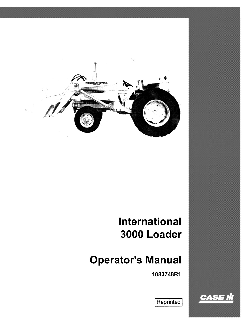
Case IH International 3000 Loader Operator’s Manual Instant Download (Publication No.1083748R1)
Please open the website below to get the complete manualnn//
Download Presentation

Please find below an Image/Link to download the presentation.
The content on the website is provided AS IS for your information and personal use only. It may not be sold, licensed, or shared on other websites without obtaining consent from the author. Download presentation by click this link. If you encounter any issues during the download, it is possible that the publisher has removed the file from their server.
E N D
Presentation Transcript
International 3000 Loader Operator's Manual 1083748R1
6 THIS SAFETY ALERT SYMBOL INDICATES IMPORTANT SAFETY MESSAGES IN THIS MANUAL. WHEN YOU SEE THIS SYMBOL, , CAREFULL Y READ THE MESSAGE THAT FOLLOWS AND BE ALERT TO THE POSSIBILITY OF PERSONAL INJURY OR DEA TH. M171B If Safety Decals on this machine use the words Danger, Warning or Caution, which are defined as follows: DANGER: Indicates an immediate hazardous situation which if not avoided, will result in death or serious injury. The color associated with Danger is RED. WARNING: Indicates an potentially hazardous situation which if not avoided, will result in serious injury. The color associated with Warning is ORANGE. CAUTION: Indicates an potentially hazardous situation which if not avoided, may result in minor or moderate injury. It may also be used to alert against unsafe practices. The color associated with Caution is YELLOW. If Safety Decals on this machine are ISO two panel Pictorial, decals are defined as follows: The first panel indicates the nature of the hazard. The second panel indicates the appropriate avoidance of the hazard. Background color is YELLOW."" 6 WARNING IMPROPER OPERATION OF THIS MACHINE CAN CAUSE INJURY OR DEATH. BEFORE USING THIS MACHINE, MAKE CERTAIN THAT EVERY OPERATOR: Prohibition symbols such as \:::I X and 8 if used, are RED. Is instructed in safe and proper use of the machine. Reads and understands the Manual(s) pertaining to the machine. Reads and understands ALL Safety Decals on the machine. Clears the area of other persons. Learns and practices safe use of machine controls in a safe, clear area before operating this machine on a job site. It is your responsibility to observe pertinent laws and regulations and follow Case Corporation instructions on machine operation and maintenance. Bur 0-00000 2001 Case Corporation issued November, 1994 CASE and IH are registered trademarks of Case Corporation
https://www.ebooklibonline.com Hello dear friend! Thank you very much for reading. Enter the link into your browser. The full manual is available for immediate download. https://www.ebooklibonline.com
To The Owner 'lour new International Harvester loader is designed to meet today1s exacting operating re- quirements. The ease of operation and the ability to adjust to field conditions lighten your work and shorten your hours on the job, tion and maximum trouble-free performance. Remember, equipment which is properly lubri- cated and adjusted saves time, labor, and fuel. After the operating season. thoroughly dean your machine and inspect it. Preventive main- tenance pays dividends. Your dealer has orig- inal-equipmentparts which assure proper fit and best performance He is able to recondition your equipment to a like new condition. 'Iou are urged to consult with your International Harvester dealer concerning un- usual field conditions. Let the experience of your dealer and the organization associated with him serve you. Be sure to read the instructions for Adjust- ing and Operating in this manual. Check each item referred to and acquaint yourself \vith the adjustments required to obtain efficient operaw Additional copies of this manual may he ordered from your International Harvester dealer at a nominal price. CONTENTS Description Description Page INTRODUCTION. Adding fluid after connect_ ing cylinders and hoses. Cold weather starting . Relief valve ... .... . Servicing the filter Loaders using tractor fluid filter. . . . Loaders using auxiliary fluid filter Torque chart .. ., .. ., Bolt Hydraulic fitting . . 8 8 <1 OPERATION. . . . . . . . . , . Ballast (counterweight) . . . Bucket level indicator .. ControLs .. .. . ... Operating hints and procedures. Digging, .. . ... . Leveling, grading, and backfilling .. .. . Load ing " ,. " N Operating speed . . . . . Safe ideas for every workday .. Tires." '" * " * .. * Transporting . . . Tractor slippage . 2 to 7 :3 3 2 4,5 ;5 8.9 8.9 7 10 7 ~ .... ., . : : 5 4 3 ~ *' .. If. .. " 6.7 3 3 ,3 SETTING UP . . . OPTIONAL EQUIPMENT. FINDING TROUBLe . . LUBRICATION SPEC!FICATIONs' 10 to 24 24 to 26 27 to 29 30 :31.32 ., ." lIP II 01: >II Ii> ., '" '*' .... 7,9 8 8,9 MAINTENANce . . . . . Daily check . . . Hydraulic system .. ... ., '*' Ii!< " '"
INTR I 3000 loader on Il'lt,O!>m,tltitJ>I'Inl 656 Trodtn. Bucket is optiono! spi Ilguoro. with Assembled in this manual are the instruc- lubrication, maintenance, for the international 3000 Loader, to operate on International 340 504, 606, Farmall 1456 and 1466 Tractors. This material has been \>/111 re efficient Whenever the terms "left" and used, it should be understood to mean from a behind and are the machine. 460 in detail in the that it The illustrations in this manual are num- bered to with the appear; for you to better understand the correct on which of your 1
OPERATION CONTROLS T I'llctor Auxltiary Volvu When it is necessary to lift a heavy load to a high and then lower it to another position before dumping, be sure to operate the control valve very carefully. Do not suddenly thrust the valve wide open and then jerk it completely closed. The heavy load will gain momentum downward when the con- trol valve is then when the valve is suddenly closed, the loader's mechanical travel is halted, but the momentum of the heavy load continues, resulting in dangerous bouncing of the load on the booms. Overcome this by slowly cracking or opening the control valve; this will release the fluid gradually and by doing so will ease the load down to the lower position desired. instead of dropping and bouncing it. Th' ! control levers will automatically return to neutral position when the levers are released. Note: lIIust.2 The inside lever controls the action of the booni. Pulling the lever back, raises the b o o m ~ Pushing it forward. lowers the boom. The outside lever controls the action of the bucket. Pulling the lever back, closes the bucket. Pushing it forward. dumps the bucket. Gmtl'lll levefs for Intemotional 2656 T roetor, with 3000 L.ooder using Vo!vos alongside Tractor Seat. The hydraulic levers on the tractor, con- trol the raising and lowering of the boom, the dumping and return to digging position of the bucket. Refer to iIIust. 2 for instructions to operate the levers. The speed with which the boom or bucket moves depends upon the movement of the con- trollevers. MOving the levers all the way back or forward will cause the fastest movement of the boom or bucket. A partial movement of the levers will slow theaetion. The lever handles are close to each other so that both levers may be operated with the right hand. at the same time. This permi.ts the operator to raise the boom and close the bucket or lower the boom and level the bucket, at the same time. while operating the tractor' with the left hand. The auxiliary valve control levers are mounted on the loader right frame which places the control levers within easy reach of the operator. _ Hlust. 2A. The degree of the bucket or the height of the boom may be held in any position by oper- ating the levers until the desired position is reached and releasing the lever so it will re- turn to neutral. Note: When the cylinders reach the fully extended or retracted position, release the control levers to the neutral position to keep excessive amounts of fluid from by passing through the relief valve and becoming over- heated. When the boom control lever is pushed all the way forward to the float position. it will stay in this position until manually released. In the float position, the boom is free to move up or down as the bucket follows the contour of the ground. This permits the operator to have both hands free to operate the tractor when leveling ground. lnust.2A L.oade .. auxiliary volve control levers.
OPERATION IUCKET LEVEL INDICATOR The loader has a bucket level indicator wbich enables the operator to see when the bucket is level. The bucket is level when the pointer is in the center of the tape on the indicator. $ .. Illust. 3 .f SA for the indicator on your loader. OPERATING SPEED The tractor engine may be operated at full throttle for normal operation. When working over rough terrain or in limited working space. reduce engine speed accordingly. Place the tractor in first gear when digging or performing heavy operations. Second gear may be used when loading. leveling, or grad- ing. TRANSPORTING When transporting. roll back the bucket and raise the boom to give the same ground clear- ance as provided by the tractor while still car- rying the bucket low enough for adequate visi- bility. TIRES A minimum of six-ply tires is recommended for the front wheels of the tractor. Refer to the table in the tractor Operator's Manual for the inflation pressure for the load. BALLAST (COUNTERWEIGHT) Weight may be added to the rear of the tractor to counterbalance the weight of the loader. Approximately Z. 000 pounds placed 50 inches behind the rear axle is recommended as ballast at the rear of the tractor. Rear- mounted weight box hts to the tractor hitch can be use as cCl'un1;erwe or TRACTOR SLIPPAGE Tractor slippage can be overcome water or calcium chloride solution in tires, or adding rear wheel weights. adding rear For adding liquid in the tires or rear wheel wetghts. refer to the tractor s Manual.
OPERADON OPERA TING HINTS AND PROCEDURES Before going downgrade. select the proper transmission gear range. In steep downhill operation, decelerate the engine and use the foot brakes if necessary to reduce the of the tractor and overspeeding the enalIUii Op.ruling Over an Obstl'Uction When crossing ditches, ridges, rocks. or logs; it must be done slowly and if possible, at an angle. This slows the fall, lessens the danger of upsetting the tractor and reduces the fall jolt which can be harmful to the ope r- ator and tractor. Decelerate the engine. then gradually increase the power as the tractor moves forward, over, and down. If the load is light. it may also be necessary to use the foot brakes. I I I J I I II r Loodins For efficiency in loading. for operating economy, and for minimizing turning and move- ments. use the V-method as shown bdUun.4. Keep the trucks close to the work area to min- imize loader tractor travel which should be held to 15 feet maximum when possible. Keep the working areas smooth. Shake the bucket only to loosen dirt from within. Approach the pile with the engine running at full governed speed. Lower the bucket so the forward motion of the tractor will push the bucket into the material. While the bucket is being pushed forward into the pile. pull the boom lever. Tben pull the bucket control lever. rolling the bucket back. This can easily be done by using both control levers at the same time. This action of "moving in" and rolling the bucket back. simultaneously is called "crowd action". Raise the bucket when moving toward the truck; and lower the bucket when moving away from the truck. The operator must learn to coordinate the use of the throttle. clutch. and transmission with that of the two bucket levers. JII1'IRltA11ONAL NARVISTIR 4
OPERATION OPERATING HINTS AND PROCEDURES. Conth'Nd Dialn, For digging. angle sufficiently to easily fill the bucket. mUlt. S8 lnust.5 Plan the excavating job so most of the work can be done with the tractor being driven for- ward out of the excavation, rather than being backed out. Use as fiat a ramp as possible. A steeper ramp can be used when driving for- ward than when driving in reverse. m"lt.5C When backfilling 01' bulldozing, never ex- tend the bucket cylinders fully and push mate- rial as shown in 1U".t. sc. Push the material as shown in !IfUlt. 58. By using the correct method. the largest amount of material will be handled in the shortest possible time, in addition to holding a level grade in the work area. Leaving the material in the bucket by not dumping it at the end of each pass will save the time of lifting, dumping. and repositioning the bucket. It win also add weight to the front end of the tractor, expecially needed if the tractor is equipped with a backhoe. Ullllt. SA For hard ground, a real" mounted scarifier is recommended to loosen the ground. before digging with the loader. Start the excavating job with the bucket tipped down. Drive the bucket into the material as far as possible without spinning the tractor wheels. By changing the position of the bucket cut- ting edge. the bucket can be lowered below ground level. After the bucket bas reached the selected depth it can be tilted upward 01' leveled off to maintain a constant depth of cut. The depth of cut to be taken will depend on the type of soil, moisture content, and tire traction of the rear wheels. Before finish grading. always remove any high spots by rough grading and by' filling holes and shaUow areas. To finish grade. run the tractor in reverse with the bucket partially open as shown lit 1111.111. 50. The loader can be used for stripping or leveling top soU. For leveling. the top of the bucket can be tipped forward and lowered as shown I. m"st. 58.. . Let dirt spill from the par- tially open bucket held close to the ground for even distribution. 5
A CAREFUL OPERATOR IS THE BEST INSURANCE AGAINST AN ACCIDENT. Do not transport a load with the bucket raised above transport position. Do not make sharp turns when backing up or at high speed with the bucket filled and raised. Avoid operating sideways on a steep slope whenever possible. Be sure the brakes are in good working order. Apply the brakes carefully on slippery roads. When using PTO driven equipment. be sure that all power line shielding is properly installed and in good order. Do not permit anyone except the operator on the machine. Do not transport anyone in the loader bucket. Comply with your state and local laws governing highway safety and with their regulations when moving machinery on a highway. Never leave the machine unattended with the engine running.
TIPS FOR SAFE OPERA nON Lower the bucket before leaving the tractor seat and before working on the loader. Add the required amoun.t of rear counterweight as recommended in this manual before operating the tractor. When working on a hillside or backing-up an incline carry the bucket low at all times. Shift tractor into low gear. When traveling over rough terrain, keep bucket low and drive slowly. Do not drive too close to edge of ditch. excavation, or where bank cave ins are possible. Keep loading area as ievel as possible. Do not use loader as iii. battering ram. Look out for overhead power lines. H it is necessary to raise the boom to work on the side or front end of the trac- tor, support the boom securely. Never allow anyone to work under a raised bucket. Set the wheels to the widths recommended in this manual. Be sure to check the safety suggestions in your tractor Operator1s Manual. MAINTENANCE HYDRAULiC fITTINGS TORQUE CHART O-RING BOSS PLUGS TUBE NUTS SWIVEL NUTS Above torque figures are recommended for plain, cadmium or zinc plated fit- tings, dry or wet installations. Swivel nuts either swaged or brazed. These torques are not recommended for tubes with waH thickness of .035 or less. 7
MAINTENANCE DAIL Y MAINTENANCE CHECK 1. All bofts and nufs; Check aU mounting bolts after every lOhours of operation. Tighten if necessary. Loose bolts cause unsatisfactory operation. excessive wear, aud strain on the tractor. Fill the reservoir with IH Hy-Tran Huid. To check the level and fill the system. follow the instructions in the tractor Operator!s Manual. Start the engine and operate it at a moderate idle speed and operate the cylinder pistons to their maximum stroke in both di- rections, about ten times. This will fill the cylinders and hoses with Huid and remove the air from the system. Set the cylinder pistons in the retracted pOSition (all the way in). Recheck the fluid level and. if necessary. add fluid up to the proper level. It will take approximately .3 gallons of hydraulic fluid in addition to tractor require- menis. Z. Coffer /lins ond loeJc,: Check all pins for loss of retainers or cotter pins. 3. Pins and bushings: All boshings are re- placeable and should be replaced if the fit be- comes noticeably loose. However, if one of a pair seems to be wearing more rapidly than the other, check to be sure it is receiving prqper lubrication. 4. Hoses and fittings: Straighten any hoses that are kinked or chafing. The hoses used are of a steel wire braid covered with rubber. It is not necessary to replace them just be- cause the metal braid is showing. Any indi- cation of either hydraulic fluid or air leak should be corrected immediately. Ssrvicing the Filter on Looders using Tractor Fluid Filter Disregard the intervals for replacing the fluid filter element in your tractor Operator's Mauual when operating the loader; use the follOwing instructions. When starting a new unit having the fluid filter in the tractor, clean the filter and replace the element after the first hour of operation. the next 50 hours, aud every 100 to lOO hours thereafter. de- pending on the nature of use of the loader. Dusty climates and material require more frequent filter changes. Service intervals cau best be determined by the individual operator. See the tractor maunal for removal instructions and instructions for checking the fluid level. Always have the cylinders re- tracted when checking the fluid level. When re-usingfluid. be sure to filter it thoroughly so that dirt is not introduced into the system. 5. Hydraulic Fluid Level: The proper fluid level should he maintained at aU times. Refer to ''Hydraulic SystemH 6. Hydraulic System Filter: Service the filter according to instructions under **Hydraulic SystemH 7 At the end of each dayfs work clean the dirt, mud. etc from the bucket. bucket ears. boom, and pivot points to prevent rust and to have the loader ready for efficient operation the next day. Sstviclng the Filter Olt Loaders using Auifiory Fluid Filter HYDRAULIC SYSTEM The loader does not require the use of the filter elements in the tractor. Use them until the auxiliary filter requires service. then remove the tractor filter elements and the retainer in the strainer and do not replace them for loader qperation. If the loader sub- frame is removed and the tractor is to be used for other operations. it will then be nee ~ euary to install hydraulic fluid filter elements in the t r a ~ t o r . UselH Hy-Tran ~ fluid in the hydraulic system. The loader uses the tractor trans- mission as the hydraulic fluid reservoir. Check and maintain the level of the hydraulic fluid according to the instructions in the tractor Operator's Manual. Keep your supply of hy- draulic fluid stored in clean containers. Wipe away aU grease and dirt before removing filler caps, plugs. or parts requiring service. Plug all open ports so dirt cannot enter, as dirt is injurious to the pump and valves. Wash all to be reassembled thoroughly in solvent. Disr-egard the time intervals shoWn in the tractor Operator's Manu'd for cleaning the screen and replacing the fluid filter elements when operating the loader. Use the following instructions! After the first hour of loader the next 50 hours. and every 100 lOO hours thereafter. depending upon the nature of use of the loader. clean the screen in the tractor and replace the filter element in the loader auxiliary fluid filter. Dusty climates and material require more frequent filter service. Service intervals can hest he determined by the individual operator. Note: When the loader is removed from the tractor aud is not to he used for some time. it is recommended that lubricant be applied to any exposed pi!!ton rod sudaces. Warm the hydraulic fluid by running the tractor engine at idling speed for sev.eral min- utes hefore operating the loader cylinders.
Suggest: If the above button click is invalid. Please download this document first, and then click the above link to download the complete manual. Thank you so much for reading
MAINTENANCE HYDRA.UlIC SYSTEM. Conti_I'd Sttrvicmg tlttt filter on loodttfS 1I$ln9 A.llxilhuy fluid fUfttr " Continue IIIV$t. fA Auxillory systflm ,.Iief volv. for tntemQflonoi 340 one! 460 T to tor .. IUU$t.9 To remove the auxiliary fluid filter ele- ment, remove the hold-down bolt "A" (lUlIst.9) from the bottom of the auxiliary filter. When replacing the filter case having a flange on the open end at liB". torque the hold-down bolt to 85-95 foot-pounds. To remove the screen, refer to the tractor Operator'sManual. To clean the screen, wash it in solvent. Re- place the gaskets. When re-using fluid. be sure to filter it thoroughly so that dirt is not introduced into the system. aefer to the tractor Operator's Manual for instructions on how to check the fluid level. must. 9. Auxillory systflm ,.tief mv. for IntemQflonol 504, 2504. 2544, 606,2606, ond 2656 TtO tors on right llde of hitch hou$h;,. (Control volvel on Internotionol 2656 TrO tof$ ON und., tit. pfotfoml.) Always have the cylinders retracted when checking the fluid level. AnUieuy System RttUef Valve The auxiliary system relief valves UU .... 'A. 98, om:! 9C) are of the cartridge-type and are not adjustable. 11 an auxiliary system relief valve malfunc- tions J remove and dismantle it; then clean all of the parts thoroughly in solvent. Be sure the hole in the orifice plate is not clogged. Reas- semble the valve, using IH Hi-Tran fluid on the O-rings.s.. ntust. 9C. If the relief valve fails to function after being cleaned. it must be re- placed with a new one. When replacing a relief valve be sure the pressure setting of the new valve is the same as the one being replaced. Relief valves have the pressure setting stamped on the head. must.9C Exploded view of ouxlliory $)'stflm ,.lief volv..
https://www.ebooklibonline.com Hello dear friend! Thank you very much for reading. Enter the link into your browser. The full manual is available for immediate download. https://www.ebooklibonline.com


