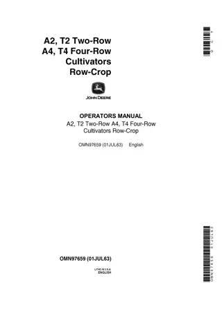
Case IH 2 and 4 Row Cultivators on Case model “CC” Tractor Operator’s Manual Instant Download (Publication No.D1117)
Please open the website below to get the complete manualnn//
Download Presentation

Please find below an Image/Link to download the presentation.
The content on the website is provided AS IS for your information and personal use only. It may not be sold, licensed, or shared on other websites without obtaining consent from the author. Download presentation by click this link. If you encounter any issues during the download, it is possible that the publisher has removed the file from their server.
E N D
Presentation Transcript
2 and 4 Row Cultivators on Case Model "CC" Tractor Operator's Manual D1117 I Reprinted I
THIS SAFETY ALERT SYMBOL INDICATES IMPORTANT SAFETY it ALERT TO THE POSSIBILITY OF PERSONAL INJURY OR DEA TH. MESSAGES IN THIS MANUAL. WHEN YOU SEE THIS SYMBOL, , CAREFULL Y READ THE MESSAGE THA T FOLLOWS AND BE M171B If Safety Decals on this machine use the words Danger, Warning or Caution, which are defined as follows: DANGER: Indicates an immediate hazardous situation which if not avoided, will result in death or serious injury. The color associated with Danger is RED. WARNING: Indicates an potentially hazardous situation which if not avoided, will result in serious injury. The color associated with Warning is ORANGE. CAUTION: Indicates an potentially hazardous situation which if not avoided, may result in minor or moderate injury. It may also be used to alert against unsafe practices. The color associated with Caution is YELLOW. If Safety Decals on this machine are ISO two panel Pictorial, decals are defined as follows: The first panel indicates the nature of the hazard. The second panel indicates the appropriate avoidance of the hazard. Background color is YELLOW.I\:\ it WARNING IMPROPER OPERATION OF THIS MACHINE CAN CAUSE INJURY OR DEATH. BEFORE USING THIS MACHINE, MAKE CERTAIN THAT EVERY OPERATOR: Prohibition symbols such as \::::I X and e if used, are RED. Is instructed in safe and proper use of the machine. Reads and understands the Manual(s) pertaining to the machine. Reads and understands ALL Safety Decals on the machine. Clears the area of other persons. Learns and practices safe use of machine controls in a safe, clear area before operating this machine on a job site. It is your responsibility to observe pertinent laws and regulations and follow Case Corporation instructions on machine operation and maintenance. Bur 0-00000 2001 Case Corporation March, 1995 (Revised October, 1997) CASE and IH are registered trade marks of Case Corporation
MR DFAL ' FR aEDUCE youa SERVICE CALLS L L Follow these instructions carefully when setting up or starting this Cultivator, then deliver book to pur- chaser and tell him to study and be guided by this valuable information ,regarding adjustment, operation and care of Cultivator. INSTRUCTIONS FOR MOUNTING; ALSO REPAIR PARTS LIST FOR THE ,CAS. Two and Four Row Cultivators on Case Model "CC" Tractor' J. L Case Company Established 1842 Racine, Wisconsin, u. s. A. Printed in U.S.A. Form DI1l7 Z500-2-31-HPCo,
https://www.ebooklibonline.com Hello dear friend! Thank you very much for reading. Enter the link into your browser. The full manual is available for immediate download. https://www.ebooklibonline.com
VARIABLE REAR WHEEL SPACING FOR "CC" TRACTOR The Model" CC' Tractor is shipped with the rear wheels in the narrow posi. tion which gives a 48-inch tread. The rear wheels are so designed that they can be reversed on the alxe and a 60-inch tread is obtained. In addition, hub ex tensions are furnished regular, and when used, a 72-inch and 84-inch tread can bf obtained by turning the wheels in or out. See illustration below for wheel s p a c i n ~ for different width of rows. 48"0.0. I I I I I I I t '------------72" Wheels Turn d In ::;:r- 1 48" Mode'''CC'' IE '----_____ 60" Wheels Turned ~ NO Extension Hub$ With Extension Hubs ~ - - - - - - - - - - - 8 4 " Wheels Turned Out With Extension Hubs Fig. 1 Variable Wheel Spacing for Different Width of Rows 2
PUTTING HUB EXTENSION ON MAIN AXLE OF "CC" TRACTOR NOTE-Hub extensions must be attached on tractor before mounting cul- tivator. See the following for attaching hub extensions. Fig. 2 1. Remove U shaped draw bar and draw bar supports from tractor. 2. Remove fenders from tractor, also remove round braces from steering column_ Do not put fenders in place until cultivator is mounted. 3. Jack up the rear axle so wheels can be removed_ CAUTION-Block tractor securely to avoid any possibility of tractor slip- ping when wheels are removed. 4. Slip hub extensions over regular hubs and attach with bolts as shown. 5. The hubs of wheels are offset so operator can set rims for wide or nan-ow track. Set wheels with nan-ow track for 3S-inch rows or less and set with wide track for rows 40-inch or "'ider. Case cultivators can be adjusted to cultivate rows from 34 to 44 inches in width, Put lugs on wheels as shO\\'n, 3
Bundles Shipped Regular Rear Cross Pipe Bracket ......................................................... . Rear and Center Cross Shafts ....................................... _ ....... . Front Cross Beam ........... _......................................................... Rear Cross Beam_ ..................... _ ........................... ", .. ,.".,_,.",_., Power Lift ......................................................................... _........ Power Lift Chain Shield............................................... .......... Front Beams (6-Shovel Pipe) ......................................... _ ..... _.. Rear Beams (6-Shovel Pipe)._ ................. _ ........................ _...... Rear Beams (6-Shovel Pipe, 4 Row Only) ..... _ .................... . Shields. _ .'."._' .... _ .. _ .............. ____ ....... _ ..... __ .... _ ................................ (2) x Spring TriplStandards (Round or Open Sleeve) ........ _ ......... (ll) x Shovels-8pearHead S.C. (Round or Open Sleeve .... _. ___ ... Gauge Wheel Att.achmenL ... _ ............... _._ .. _. _ _ .... __ .. ____ .... _ .... _ . Two Row Four Row x x x x x x (2) x x x (4) x (21) x. x (2) x x x x x x x x x x Extra Equipment Disk Hiller Attachment (12-in. Disks) 6-in. Sandy Land Sweeps 8-in. Sandy Land Sweeps Flat Shields Weed Knife Attachment. No. 80 Disk Hiller Attachment (16-in. Disk) Rota1"y Hoe Attachment Spring Tooth Attachment Vine Shields for Wheels Parts to Change 2-I"OW to 4-row 4
Fig. 3 TO ATTACH POWER LIFT Power Lift is attached to right forward side of main axle of tractor. Remove the grease cup or pipe plug from right forward side of ma!n axle housing. Screw short pipe with elbow in p l a ~ e and use this pipe fts a guide when putting power lift in place. Remove elbow from end of pipe. 1. Put power lift in place over pipe on front side of axle and secure with two large "U" bolts but do not tighten nuts on upper legs of "U" bolts. , . Replace elbow on grease pipe and screw grease cup in elbow. CAUTION-Turn grease cup slightly down so it will not interfere when power lift revolves. 3. Screw oil cups (found in bag) in bearings as shown. Thoroughly oil the bear- ings and keep them well oiled. 4. Remove cotters and both side links in drive chain and place chain around sprockets and connect ends. 5. Bolt power lift foot lever in place. NOTE-Bolt should be screwed in lever pivot and locked with washer and nut. Place spring on small bolts on front end of power lift and foot lever. 6. See No.6-Fig. 7. Remove two stove bolts in band (not shown) on rear of chain shield. Place shield around axle and replace stove bolts before at- t.aching shield to "U" bolts. Place power lift chain shield in position and secure to upper legs of "U" bolts holding power lift in place. CAUTION-Turn nuts tight on "u" bolts to hold power lift firmly in place. 5
Suggest: If the above button click is invalid. Please download this document first, and then click the above link to download the complete manual. Thank you so much for reading
Fig. 4 TO ATTACH CENTER CROSS SHAFT 7. R.emove the parts from one end of square center cross shaft, opposite 1 end with extension quadrant. Slide shaft through traetor from right ha side and bolt bearing bracket. on shaft to front side of center cross angle w bolts. (Do not tighten outside bolt). ( ; ) ~ C ; P ( i 6 ) '\ , : ",1 I /II1:f " . , I I I I " ' Fig. 5 6
https://www.ebooklibonline.com Hello dear friend! Thank you very much for reading. Enter the link into your browser. The full manual is available for immediate download. https://www.ebooklibonline.com

