CASE IH 12.9L Engine Service Repair Manual Instant Download (Part Number 87523642)
CASE IH 12.9L Engine Service Repair Manual Instant Download (Part Number 87523642)

Uploaded on | 0 Views
Download Presentation

Please find below an Image/Link to download the presentation.
The content on the website is provided AS IS for your information and personal use only. It may not be sold, licensed, or shared on other websites without obtaining consent from the author. Download presentation by click this link. If you encounter any issues during the download, it is possible that the publisher has removed the file from their server.
E N D
Presentation Transcript
Case IH 12.9L Engine Repair Manual 87523642
1 E NGINE Section 1 General specifications 2 Fuel 3 Industrial application 4 Overhaul and technical specifications 5 Tools Appendix Safety prescriptions PREFACE TO USER S GUIDELINE MANUAL Section 1 describes the engine illustrating its features and working in general. Section 2 describes the type of fuel feed. Section3relatestothespecificdutyandisdividedinfoursepa- rate parts: 1. Mechanical part, related to the engine overhaul, limited to those components with different characteristics based on the relating specific duty. 2. Electrical part, concerning wiring harness, electrical and electronic equipment with different characteristics based on the relating specific duty. 3. Maintenance planning and specific overhaul. 4. Troubleshooting part dedicated to the operators who, beingentitledtoprovidetechnicalassistance,shallhavesimple anddirectinstructionstoidentifythecauseofthemajorincon- veniences. Sections4and5 illustratetheoverhauloperationsoftheengi- neoverhaulonstandandthenecessaryequipmenttoexecute such operations.
1 SECTION 1 - GENERAL SPECIFICATIONS SECTION 1 General Specifications Page TECHNICAL CODE . . . . . . . . . . . . . . . . . . . . . . 3 VIEWS OF ENGINE . . . . . . . . . . . . . . . . . . . . . . 5 LUBRICATION DIAGRAM . . . . . . . . . . . . . . . . . 8 - Oil pump . . . . . . . . . . . . . . . . . . . . . . . . . . . . . 9 - Overpressure valve . . . . . . . . . . . . . . . . . . . . . 9 - Oil pressure control valve . . . . . . . . . . . . . . . . 10 - Heat exchanger . . . . . . . . . . . . . . . . . . . . . . . . 10 - By-pass valve . . . . . . . . . . . . . . . . . . . . . . . . . . 11 - Thermostatic valve . . . . . . . . . . . . . . . . . . . . . . 11 - Engine oil filters . . . . . . . . . . . . . . . . . . . . . . . . 11 COOLING . . . . . . . . . . . . . . . . . . . . . . . . . . . . . 12 - Water pump . . . . . . . . . . . . . . . . . . . . . . . . . . 13 - Thermostat . . . . . . . . . . . . . . . . . . . . . . . . . . . 13 TURBOCHARGING . . . . . . . . . . . . . . . . . . . . . . 14
https://www.ebooklibonline.com Hello dear friend! Thank you very much for reading. Enter the link into your browser. The full manual is available for immediate download. https://www.ebooklibonline.com
2 SECTION 1 - GENERAL SPECIFICATIONS
3 SECTION 1 - GENERAL SPECIFICATIONS TEC H N I C A L C O D E Technical Code F3BE0684H*E901 F3BE0684G*E901
4 SECTION 1 - GENERAL SPECIFICATIONS
5 SECTION 1 - GENERAL SPECIFICATIONS VIEWS OF ENGINE Figure 1 104272 LEFT-HAND SIDE VIEW Figure 2 104273 RIGHT-HAND SIDE VIEW
6 SECTION 1 - G ENERAL SP ECIFICATIONS VIEWS OF ENGINE Figure 3 104274 FRONT VIEW Figure 4 104275 REAR VIEW
7 SECTION 1 - GENERAL SPECIFICATIONS VIEW OF ENGINE Figure 5 104276 TOP VIEW
8 SECTION 1 - G ENERAL SP ECIFICATIONS LUBRICATION DIAGRAM Figure 6 Dropping oil Pressure oil 104277
9 SECTION 1 - GENERAL SPECIFICATIONS Overpressure valve Oil pump Figure 7 Figure 9 60560 73540 The oil pump (1) cannot be overhauled. On finding any damage, replace the oil pump assembly. MAIN DATA TO CHECK THE OVERPRESSURE VALVE SPRING See under the relevant heading for replacing the gear (2) of the crankshaft. Figure 8 1 73541 OIL PUMP CROSS-SECTION 1. Overpressure valve Start of opening pressure 10.1 0.7 bars.
10 SECTION 1 - G ENERAL SP ECIFICATIONS Oil pressure control valve Figure 11 Figure 10 73542 73543 Theoilpressurecontrolvalve islocated on the left-handside of the crankcase. Start of opening pressure 5 bars. MAIN DATA TO CHECK THE OIL PRESSURE CONTROL VALVE SPRING Heat exchanger Figure 12 104236 HEAT EXCHANGER The heat exchanger is fitted with: 1. Oil pressure/temperature sensor - 2. By-pass valve - 3. Heat valve.
11 SECTION 1 - GENERAL SPECIFICATIONS This is a new generation of filters that permit much more thorough filtration as they are able to holder back a greater amount of particles of smaller dimensions than those held back by conventional filters with a paper filtering element. By-pass valve Figure 13 These high-filtration devices, to date used only in industrial processes, make it possible to: - reduce the wear of engine components over time; - maintain the performance/specifications of the oil and thereby lengthen the time intervals between changes. External spiral winding The filtering elements are closely wound by a spiral so that each fold is firmly anchored to the spiral with respect to the others. This produces a uniform use of the element even in the worst conditions such as cold starting with fluids with a high viscosity and peaks of flow. In addition, it ensures uni- form distribution of the flow over the entire length of the filtering element,with consequentoptimization ofthe lossof load and of its working life. 73545 The valve quickly opens at a pressure of: 3 bars. Thermostatic valve Figure 14 Mount upstream To optimize flow distribution and the rigidity of the filtering el- ement,thishasan exclusivemountcomposed ofa strongmesh made of nylon and an extremely strong synthetic material. Filtering element Composed of inert inorganic fibres bound with an exclusive resin to a structure with graded holes, the element is manu- factured exclusively to precise procedures and strict quality control. 73546 Start of opening: - travel 0.1 mm at a temperature of 82 2 C. End of opening: - travel 8 mm at a temperature of 97 C. Mount downstream A mount for the filtering element and a strong nylon mesh make it even stronger, which is especially helpful during cold starts and long periods of use. The performance of the filter remains constant and reliable throughout its working lifeand from one element to another, irrespective of the changes in working conditions. Engine oil filters Figure 15 Structural parts The o-rings equipping the filtering element ensure a perfect seal between it and the container, eliminating by-pass risks and keeping filter performance constant. Strong corrosion- proofbottomsandasturdy internalmetalcorecompletethe structure of the filtering element. When mounting the filters, keep to the following rules: - Oil and fit new seals. - Screw down the filters to bring the seals into contact with the supporting bases. - Tighten the filter to a torque of 35-40 Nm. 47447
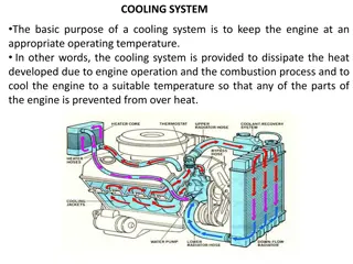
12 SECTION 1 - G ENERAL SP ECIFICATIONS COOLING Figure 16 Water flowing out of the thermostat Water circulating in the engine Water flowing into the pump 104278
13 SECTION 1 - GENERAL SPECIFICATIONS Water pump Figure 19 Figure 17 TO THE RADIATOR TO THE EXPANSION TUB TO THE BY PASS FROM THE ENGINE 60748 Water leaving the thermostat 104239 Check the thermostat works properly; replace it if in doubt. Temperature of start of travel 84 C 2 C. Minimum travel 15 mm at 94 C 2 C. CROSS-SECTION OF THE WATER PUMP The water pump comprises: rotor, shaft with bearing. T-gasket and drive pulley. Check that the pump body has no cracks or water leakage; if it does, replace the entire water pump. ! Thermostat View of thermostat operation Figure 18 TO THE RADIATOR TO THE EXPANSION TUB FROM TO THE BY PASS THE ENGINE 60747 Water circulating in the engine
Suggest: For more complete manuals. Please go to the home page. https://www.ebooklibonline.com If the above button click is invalid. Please download this document first, and then click the above link to download the complete manual. Thank you so much for reading
14 SECTION 1 - G ENERAL SP ECIFICATIONS TURBOCHARGING The turbocharging system consists of: - air filter; - turbocharger. Figure 20 Exhaust gas Inlet air Compressed air (hot) Intake compressed air 104279 TURBOCHARGER HX55
1 SECTION 2 - FUEL SECTION 2 Fuel Page FEEDING . . . . . . . . . . . . . . . . . . . . . . . . . . . . . . . 3 FUEL SUPPLY DIAGRAM . . . . . . . . . . . . . . . . . . 4 - Fuel pump . . . . . . . . . . . . . . . . . . . . . . . . . . . . 5 - Injector-pump . . . . . . . . . . . . . . . . . . . . . . . . . 5
https://www.ebooklibonline.com Hello dear friend! Thank you very much for reading. Enter the link into your browser. The full manual is available for immediate download. https://www.ebooklibonline.com