CASE CX290 CRAWLER EXCAVATOR Service Repair Manual Instant Download
Please open the website below to get the complete manualnn// n

Download Presentation

Please find below an Image/Link to download the presentation.
The content on the website is provided AS IS for your information and personal use only. It may not be sold, licensed, or shared on other websites without obtaining consent from the author. Download presentation by click this link. If you encounter any issues during the download, it is possible that the publisher has removed the file from their server.
E N D
Presentation Transcript
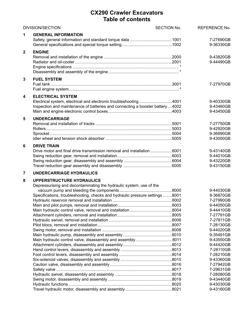
CX290 Crawler Excavators Table of contents DIVISION/SECTION SECTION No. REFERENCE No. 1 GENERAL INFORMATION Safety, general information and standard torque data.....................................1001 General specifications and special torque setting............................................1002 7-27690GB 9-36330GB 2 ENGINE Removal and installation of the engine............................................................2000 Radiator and oil-cooler.....................................................................................2001 Engine specifications .............................................................................................* Disassembly and assembly of the engine..............................................................* 9-43820GB 9-44490GB 3 FUEL SYSTEM Fuel tank..........................................................................................................3001 Fuel engine system................................................................................................* 7-27970GB 4 ELECTRICAL SYSTEM Electrical system, electrical and electronic troubleshooting.............................4001 Inspection and maintenance of batteries and connecting a booster battery....4002 Main and engine electronic control boxes........................................................4003 9-40330GB 9-43460GB 9-43450GB 5 UNDERCARRIAGE Removal and installation of tracks ...................................................................5001 Rollers..............................................................................................................5003 Sprocket...........................................................................................................5004 Idler wheel and tension shock absorber ..........................................................5005 7-27750GB 9-42920GB 9-36890GB 9-43000GB 6 DRIVE TRAIN Drive motor and final drive transmission removal and installation...................6001 Swing reduction gear, removal and installation................................................6003 Swing reduction gear, disassembly and assembly ..........................................6004 Travel reduction gear assembly and disassembly...........................................6005 9-43140GB 9-44010GB 9-43220GB 9-43150GB 7 UNDERCARRIAGE HYDRAULICS 8 UPPERSTRUCTURE HYDRAULICS Depressurising and decontaminating the hydraulic system, use of the vacuum pump and bleeding the components..............................................8000 Specifications, troubleshooting, checks and hydraulic pressure settings ........8001 Hydraulic reservoir removal and installation ....................................................8002 Main and pilot pumps, removal and installation...............................................8003 Main hydraulic control valve, removal and installation.....................................8004 Attachment cylinders, removal and installation................................................8005 Hydraulic swivel, removal and installation .......................................................8006 Pilot blocs, removal and installation.................................................................8007 Swing motor, removal and installation .............................................................8008 Main hydraulic pump, disassembly and assembly...........................................8010 Main hydraulic control valve, disassembly and assembly................................8011 Attachment cylinders, disassembly and assembly...........................................8012 Hand control levers, disassembly and assembly.............................................8013 Foot control levers, disassembly and assembly ..............................................8014 Six-solenoid valves, disassembly and assembly .............................................8015 Caution valve, disassembly and assembly ......................................................8016 Safety valve .....................................................................................................8017 Hydraulic swivel, disassembly and assembly..................................................8018 Swing motor, disassembly and assembly........................................................8019 Hydraulic functions...........................................................................................8020 Travel hydraulic motor, disassembly and assembly.........................................8021 9-44030GB 9-36870GB 7-27990GB 9-44050GB 9-44410GB 7-27791GB 7-27811GB 7-28130GB 9-44020GB 9-35491GB 9-43550GB 9-44420GB 7-28110GB 7-28210GB 9-43360GB 7-27942GB 7-29631GB 7-28080GB 9-43440GB 9-43030GB 9-43160GB
DIVISION/SECTION SECTION No. REFERENCE No. 9 UPPERSTRUCTURE Upperstructure, turntable and counterweight...................................................9002 Boom, dipper and bucket.................................................................................9003 Seat and seat belt............................................................................................9004 Cab and cab equipment...................................................................................9005 Air conditioning troubleshooting.......................................................................9006 Air conditioning unit disassembly and assembly..............................................9007 Air conditioning servicing .................................................................................9008 Air conditioning components............................................................................9009 Large format hydraulic and electrical schematics.........................................Pocket 9-43760GB 9-27961GB 9-40960GB 9-43750GB 7-xxxxxFR 7-29910GB 7-xxxxxFR 7-xxxxxFR 7-27622GB * Consult the Engine Service Manual Sections to be distributed at a later date NOTE: CASE Company reserves the right to make changes in the specifi- cation and design of the machine without prior notice and without incurring any obligation to modify units previously sold. The description of the models shown in t his manual has been m ade in accordance with the technical specifications known as of the date of design of this document. Cre 9-44510GB Issued 04-02
1001 Section 1001 SAFETY, GENERAL INFORMATION AND STANDARD TORQUE DATA Case Cre 7-27690GB
1001-2 TABLE OF CONTENTS GENERAL INFORMATION.......................................................................................................................................3 SAFETY.....................................................................................................................................................................4 STANDARD TORQUE DATA FOR CAP SCREWS AND NUTS...............................................................................6 Cre 7-21930GB Issued 01-99 Printed in U.K.
https://www.ebooklibonline.com Hello dear friend! Thank you very much for reading. Enter the link into your browser. The full manual is available for immediate download. https://www.ebooklibonline.com
1001-3 GENERAL INFORMATION Cleaning Gears Clean all metal parts except bearings, in a s uitable cleaning so lvent or by steam cl eaning. Do not us e caustic soda for steam cleaning. After cleaning, dry and put oil on al l pa rts. Clean oi l passages wi th compressed air. Clean bearings in a suitable cleaning solvent. Dry the bearings completely and put oil on the bearings. Check all gears for wear and damage. Replace gears that have wear or damage. Oil Seals, O-rings and Gaskets Always install new oil seals, O-rings and gaskets. Put petroleum jelly on seals and O-rings. Shafts Inspection Check all shafts that have wear or damage. Check the be aring an d o il s eal s urfaces o f th e s hafts for damage. Check all parts wh en the parts ar e di sassembled. Replace all parts that have wear or damage. Small scoring or grooves can be removed with a hone or crocus c loth. Com plete a v indications o f we ar, pitting an d th e r eplacement of parts necessary to prevent early failures. isual i nspection for Service Parts Always i nstall genuine C ase s ervice parts. W hen ordering refer to the Parts Catalog for the correct part number of the genuine Cas e r eplacement ite ms. Failures due to the use of other than genuine Case replacement parts are not covered by warranty. Bearings Check bearings for easy action. If be arings have a loose fit or rough action, replace the bearing. Wash bearings with a suitable cleaning solvent and permit to ai r dry . DO NOT DR Y BEARINGS WITH COMPRESSED AIR. Lubrication Only u se the oils and lu bricants s pecified i n th e Operator s or Service Manuals. Failures due to th e use of n on-specified oils an d lu bricants ar e no t covered by warranty. Needle Bearings Before you press needle bearings in a bore always remove any metal protrusions in the bore or edge of the bore. Before you press bearings into position, put petroleum jelly on the inside and outside diameter of the bearings. Cre 7-27690GB Issued 09-00
1001-4 SAFETY This symbol means ATTENTION! BECOME ALERT! YOUR SAFETY IS INVOLVED. The message that follows the symbol contains important information about safety. Carefully read the message. Make sure you fully understand the causes of possible injury or death. ! To prevent injury always follow the Warning, Caution and Danger notes in this section and throughout the manual. WARNING: Before starting engine, study Operator s Manual safety messages. Read all safety signs on machine. Clear the area of other persons. Learn and practice safe use of controls before operating. It is your responsibility to understand and follow manufacturers instructions on machine operation, service and to observe pertinent laws and regulations. Operator s and Service Manuals may be obtained from your Case dealer. Place a Do not operate tag on the starter switch key before carrying out any service or repair work on the machine. ! . WARNING: Read the operator s manual to familiarize yourself with the correct control functions. ! WARNING: Operate the machine and equipment controls from the seat position only. Any other method could result in serious injury. WARNING: If you wear clothing that is too loose or do not use the correct safety equipment for your job, you can be injured. Always wear clothing that will not catch on objects. Extra safety equipment that can be required includes hard hat, safety shoes, ear protection, eye or face protection, heavy gloves and reflector clothing. ! ! WARNING: This is a one man machine, no riders allowed. ! WARNING: When working in the area of the fan belt with the engine running, avoid loose clothing if possible, and use extreme caution. ! WARNING: When doing checks and tests on the equipment hydraulics, follow the procedures as they are written. DO NOT change the procedure. ! WARNING: When putting the hydraulic cylinders on this machine through the necessary cycles to check operation or to remove air from a circuit, make sure all people are out of the way. ! Cre 7-27690GB Issued 09-00
1001-5 WARNING: When servicing or repairing the machine, keep the shop floor and operator s compartment and steps free of oil, water, grease, tools, etc. Use an oil absorbing material and/or shop cloths as required. Use safe practices at all times. WARNING: Use insulated gloves or mittens when working with hot parts. ! ! WARNING: Lower all attachments to the ground or use stands to safely support the attachments before you do any maintenance or service. ! WARNING: Some components of this machine are very heavy. Use suitable lifting equipment or additional help as instructed in this Service Manual. ! WARNING: Pin sized and smaller streams of hydraulic oil under pressure can penetrate the skin and result in serious infection. If hydraulic oil under pressure does penetrate the skin, seek medical treatment immediately. Maintain all hoses and tubes in good condition. Make sure all connections are tight. Make a replacement of any tube or hose that is damaged or thought to be damaged. DO NOT use your hand to check for leaks, use a piece of cardboard or wood. WARNING: Engine exhaust fumes can cause death. If it is necessary to start the engine in a closed place, remove the exhaust fumes from the area with an exhaust pipe extension. Open the doors and get outside air into the area. ! ! WARNING: When the battery electrolyte is frozen, the battery can explode if (1), you try to charge the battery, or (2), you try to jump start and run the engine. To prevent the battery electrolyte from freezing, try to keep the battery at full charge. If you do not follow these instructions, you or others in the area can be injured. WARNING: When removing hardened pins such as a pivot pin, or a hardened shaft, use a soft head (brass or bronze) hammer or use a driver made from brass or bronze and a steel head hammer. ! ! WARNING: When using a hammer to remove and install pivot pins or separate parts using compressed air or using a grinder, wear eye protection that completely encloses the eyes (approved goggles or other approved eye protectors). ! WARNING: Use suitable floor (service) jacks or chain hoist to raise wheels or tracks off the floor. Always block machine in place with suitable safety stands. ! Cre 7-27690GB Issued 09-00
1001-6 STANDARD TORQUE DATA FOR CAP SCREWS AND NUTS Tightening of Cap Screws and Nuts Tighten alternately so that tightening torque can be applied evenly. The numbers in the figure below indicate the order of tightening. JS00481A Cap screws which have had Loctite used (white residue remains after removal) should be cleaned with light oil or suitable cleaning solvent and dried. Apply 2-3 drops of Lo ctite to the thread portion of the c ap screw and then tighten. Cre 7-27690GB Issued 09-00
1001-7 Torque Table Tighten cap screws and nuts according to the table below if there are no other special instructions. Cap Screw Name Size (Size) M6 M8 M10 M12 M14 M16 M18 M20 [mm] 10 13 17 19 22 24 27 30 Spanner [in.] 0.39 0.51 0.67 0.75 0.87 0.95 1.06 1.18 Cap Screw [Nm] 6.9 19.6 39.2 58.8 98.1 157.2 196.0 274.0 Tightening torque [lb-ft] 5.1 14.5 29.0 43.4 72.5 116.0 144.6 202.4 [mm] 5 6 8 10 12 14 14 17 Spanner Socket Head Cap Screw [in.] 0.20 0.24 0.32 0.39 0.47 0.55 0.55 0.67 [Nm] 8.8 21.6 42.1 78.4 117.6 176.4 245.0 343.0 Tightening torque [lb-ft] 6.5 15.9 31.1 57.8 86.8 130.1 180.8 253.1 Cre 7-27690GB Issued 09-00
1001-8 NOTES ..................................................................................................................................................................................... ..................................................................................................................................................................................... ..................................................................................................................................................................................... ..................................................................................................................................................................................... ..................................................................................................................................................................................... ..................................................................................................................................................................................... ..................................................................................................................................................................................... ..................................................................................................................................................................................... ..................................................................................................................................................................................... ..................................................................................................................................................................................... ..................................................................................................................................................................................... ..................................................................................................................................................................................... ..................................................................................................................................................................................... ..................................................................................................................................................................................... ..................................................................................................................................................................................... ..................................................................................................................................................................................... ..................................................................................................................................................................................... ..................................................................................................................................................................................... ..................................................................................................................................................................................... ..................................................................................................................................................................................... ..................................................................................................................................................................................... ..................................................................................................................................................................................... ..................................................................................................................................................................................... ..................................................................................................................................................................................... ..................................................................................................................................................................................... ..................................................................................................................................................................................... ..................................................................................................................................................................................... ..................................................................................................................................................................................... ..................................................................................................................................................................................... ..................................................................................................................................................................................... ..................................................................................................................................................................................... ..................................................................................................................................................................................... ..................................................................................................................................................................................... ..................................................................................................................................................................................... ..................................................................................................................................................................................... ..................................................................................................................................................................................... ..................................................................................................................................................................................... Cre 7-27690GB Issued 09-00
Section 1002 1002 SPECIFICATIONS AND SPECIAL TORQUE SETTINGS Case Cre 9-36330GB
1002-2 TABLE OF CONTENTS TYPE, SERIAL NUMBER AND YEAR OF MANUFACTURE OF THE MACHINE....................................................3 Machine.................................................................................................................................................................3 Engine...................................................................................................................................................................3 Serial numbers of the components .......................................................................................................................3 INGREDIENTS..........................................................................................................................................................4 Hydraulic fluid .......................................................................................................................................................4 Transmission assembly oil ...................................................................................................................................4 Greases ................................................................................................................................................................4 Engine oil ..............................................................................................................................................................5 Viscosity of oils/Operating range of oils ................................................................................................................5 Fuel ......................................................................................................................................................................6 Antifreeze/anticorrosive ........................................................................................................................................6 Environment .........................................................................................................................................................6 Plastic and resin parts ..........................................................................................................................................6 SPECIFICATIONS.....................................................................................................................................................7 Engine...................................................................................................................................................................7 Capacities .............................................................................................................................................................7 Electrical system ...................................................................................................................................................7 Hydraulic system...................................................................................................................................................8 Cylinder.................................................................................................................................................................8 Control valve .........................................................................................................................................................9 Swing ....................................................................................................................................................................9 Travel....................................................................................................................................................................9 Undercarriage .......................................................................................................................................................9 Attachment............................................................................................................................................................9 Weight of components ........................................................................................................................................10 DIMENSIONS AND WEAR LIMIT OF THE TRACK ASSEMBLY ...........................................................................11 Sprocket..............................................................................................................................................................11 Idler wheel...........................................................................................................................................................12 Upper roller .........................................................................................................................................................13 Lower roller .........................................................................................................................................................14 Track ...................................................................................................................................................................15 DIMENSIONS AND WEAR LIMITS OF ATTACHMENT LINKAGES ......................................................................16 Boom foot/Frame ................................................................................................................................................16 Boom cylinder foot/Frame...................................................................................................................................17 Boom cylinder head/Boom..................................................................................................................................17 Dipper cylinder foot/Boom...................................................................................................................................18 Boom/Dipper .......................................................................................................................................................18 Dipper cylinder head/Dipper................................................................................................................................18 Bucket cylinder foot/Dipper .................................................................................................................................19 Connecting rod/Dipper ........................................................................................................................................19 Compensator/Bucket...........................................................................................................................................19 Connecting rod/Compensator/Bucket cylinder head...........................................................................................20 Dipper/Bucket......................................................................................................................................................20 SPECIAL TORQUE SETTINGS..............................................................................................................................21 MACHINE OVERALL DIMENSIONS.......................................................................................................................24 WARNING: This symbol is used in this manual to indicate important safety messages. Whenever you see this symbol, carefully read the message which follows. Your safety depends on it. ! Cre 9-36330GB Issued 12-01
1002-3 TYPE, SERIAL NUMBER AND YEAR OF MANUFACTURE OF THE MACHINE For all part orders, request for information or assistance, always specify the type and the serial number of the machine to your CASE dealer. Fill in the following lines with the required information: Type, serial number, year of manufacture of the machine and the serial numbers of the hydraulic and mechanical components. Machine 1 3 2 CP98N006 CS01J532 (1) Type............................................................................. (2) Serial number.............................................................. (3) Year of manufacture.................................................... Engine Make and type............................................................................................................................................................. Serial number.............................................................................................................................................................. Serial numbers of the components Hydraulic pump............................................................................................................................................................ Swing reduction gear................................................................................................................................................... Travel reduction gears ................................................................................................................................................. Travel control valve ...................................................................................................................................................... Attachment control valve ............................................................................................................................................. Swing control valve...................................................................................................................................................... Cre 9-36330GB Issued 12-01
1002-4 INGREDIENTS The ingredients must correspond to specific characteristics for every usage. WARNING: You must respect the operating conditions for the different ingredients. ! Hydraulic fluid Greases The CASE hydraulic fluid is specially adapted for high pressure and CASE s hydraulic circuit. The type of fluid to be used depends on the ambient temperature. Temperate climates The type of grease to be used depends on the ambient temperature. Hot and temperate climates -20 C to +60 C Extreme pressure EP NLGI grade 2 grease with molybdenum disulfide. Cold climates -20 C to +40 C Fluid type: ISO VG 46 CASE reference: POHYDR Hot climates -40 C to +20 C Extreme pressure EP NLGI grade 0 grease. 0 C to +60 C Fluid type: ISO VG 100 CASE reference: POHYPC Cold climates -40 C to +20 C Fluid type: ISO VG 22 CASE reference: POHYPF Temperate climate biodegradable fluid: This yellow-coloured fluid is miscible with standard fluid. When introducing this fluid, it is recommended to drain the hydraulic system completely. Fluid type: ISO VG 46 CASE reference: CASYNTH 46 These different grades of fluids must comply with the CASE specification. Transmission assembly oil Extreme assemblies in housing. Extreme pressure oil TYPE API GL5 GRADE 80W90 and ISO VG 150 pressure oil used for transmission Cre 9-36330GB Issued 12-01
1002-5 Engine oil The CASE No.1 engine oil is recommended for your engine. This oil ensures proper lubrication of your engine for all operating conditions. If you are unable to procure the CASE No.1 Multiperformance or Performance engine oil, use the corresponding oil from the API/CG/CF category. NOTE: Do not put any performance additives or any other additives in the engine housing. The oil changing intervals are indicated in this manual based on tests carried out on CASE lubricants. RD97F136 RD97F100 Viscosity of oils/Operating range of oils A 3 1 2 4 B CS98M561 (A) FAHRENHEIT TEMPERATURE (B) CELSIUS TEMPERATURE (1) ALL SEASONS (*) SHOWS THAT IT IS NECESSARY TO USE AN ENGINE OIL HEATER OR THERMAL COOLER. (2) WINTER (3) TROPICAL (4) ARCTIC Cre 9-36330GB Issued 12-01
1002-6 Fuel Environment The fuel to be used must comply with the D975 norm of the American Society for Testing and Materials (ASTM). Before carrying out any maintenance operation on this machine and before throwing away the liquids or lubricants used, always think of the environment. Never throw oil or liquids on the ground and never put them in leaking containers. Use type No.2 fuel, use of other fuels can cause a loss of engine power consumption. and excessive fuel Consult your local centre for ecological recycling for information on the appropriate method for disposing off these substances. In cold weather, it is provisionally accepted that a mixture of No.1 and No.2 fuels be used. Contact your fuel supplier. Plastic and resin parts If the temperature drops below the freezing point of the fuel (point where paraffin appears), paraffin crystals in the fuel will cause loss of engine power or starting trouble. When cleaning plastic parts, on the console, the instrument panel, the indicator and gauges etc., do not use petrol, paraffin, paint solvents, etc. Use only water, soap and a soft cloth. IMPORTANT: In cold weather, fill up the reservoir with fuel after each workday, in order to avoid the formation of condensation. Storing fuel The use of petrol, paraffin, paint solvents etc... causes discoloration, cracks or deformation of these parts. Prolonged storage of fuel promotes the accumulation of foreign bodies or condensed moisture in the storage tank. Many engine failures are caused by the presence of water in fuel. The storage tank must be placed outside and the fuel should be maintained at as low a temperature as possible. Drain the condensed moisture at regular intervals. Antifreeze/anticorrosive Use the antifreeze in all seasons to protect the coolant system from corrosion and to avoid any risk of freezing. In environments with a temperature greater than -36 C, use a 50% mixture of antifreeze in an ethylene glycol base. In environments with a temperature less than -36 C, it is recommended that you use a 40% water and 60% antifreeze mixture. Cre 9-36330GB Issued 12-01
1002-7 SPECIFICATIONS CX290 Engine Make................................................................................................................................................................... Isuzu Model.........................................................................................................................................................CC-6BG1T Type: Four stroke, water cooled with overhead valves, direct injection in-line cylinder (electronic control) with turbocharger. Number of cylinders...................................................................................................................................................6 Bore and stroke ....................................................................................................................................105 x 125 mm Displacement..................................................................................................................................................6494 cc Operating conditions Idle................................................................................................................................................................1000 rpm Max speed....................................................................................................................................................2200 rpm Power ECC 1289.......................................................................................................................... 140.5 kW (191 HP) Max torque...............................................................................................................................676.2 Nm at 1800 rpm Capacities Engine oil capacity..........................................................................................................................................24 litres Engine cooling circuit......................................................................................................................................29 litres Capacity of only the radiator ..........................................................................................................................20 litres Fuel reservoir................................................................................................................................................ 340 litres Hydraulic fluid reservoir capacity.................................................................................................................. 120 litres Total hydraulic circuit capacity...................................................................................................................... 240 litres Capacity of only the oil-cooler ..................................................................................................................... 15.7 litres Travel reduction gear housing capacity .........................................................................................................4.7 litres Swing drive housing capacity ........................................................................................................................... 6 litres Idler pulley capacity.......................................................................................................................................... 250 cc Upper roller capacity.............................................................................................................................. 245 to 250 cc Lower roller capacity......................................................................................................................................... 280 cc NOTE: These capacities are given only for information purposes. To check the fluid levels, always use the oil gauge, visual gauges or the filler cap. Electrical system Type of system.........................................................................................................................24 volts earth negative Alternator amperage.................................................................................................................................50 amperes Battery Number of batteries required ................................................................................................................................2 Voltage of each battery ...............................................................................................................................12 volts Capacity ...................................................................................................................................................... 112 Ah Reserve......................................................................................................................................................160 min Cold startability at -17 .................................................................................................................................. 800 A Load for load control...................................................................................................................................... 400 A Starter Voltage ........................................................................................................................................................24 volts Power ...........................................................................................................................................................4.5 kW Voltage regulator .............................................................................................................. built-in, without adjustment Cre 9-36330GB Issued 12-01
1002-8 CX290 Hydraulic system Main hydraulic pump Variable flow double pump, with axial pistons. Maximum flow......................................................................................................................................... 2 x 221 l/min Displacement............................................................................................................................................. 2 x 97.2 cc Hydraulic pilot pump Fixed flow pump Max flow ...................................................................................................................................................... 22.3 l/min Displacement...................................................................................................................................................... 10 cc Pressure setting Pilot circuit relief ..........................................................................................................................................39 1 bar Main circuit relief (standard)......................................................................................................................343 3 bar Main circuit relief (power-up) .....................................................................................................................373 5 bar Secondary relief (boom, dipper and bucket)..............................................................................................392 5 bar Secondary relief (swing)............................................................................................................................294 4 bar Secondary relief (travel) ............................................................................................................................380 5 bar Safety valve (boom and dipper).................................................................................................................392 5 bar Cylinder Boom cylinder Cylinder bore..................................................................................................................................................135 mm Rod diameter....................................................................................................................................................95 mm Stroke ...........................................................................................................................................................1369 mm Dipper cylinder Cylinder bore..................................................................................................................................................150 mm Rod diameter..................................................................................................................................................105 mm Stroke ...........................................................................................................................................................1438 mm Bucket cylinder Cylinder bore..................................................................................................................................................130 mm Rod diameter....................................................................................................................................................90 mm Stroke ...........................................................................................................................................................1073 mm Cylinder leakage - attachment lowering (without load) Boom cylinders (rods retracted) ...............................................................................................................3 mm/5 min Dipper cylinder (rod extended) .................................................................................................................5 mm/5 min Dipper cylinder (rod extended) .................................................................................................................7 mm/5 min Total (at the end of the attachment)......................................................................................................200 mm/5 min Cylinder speed (in S mode) Boom raised (bucket open and on the ground) .....................................................................................4.6 0,6 sec. Boom lowered (bucket open).................................................................................................................3.7 0.6 sec. Dipper extended ....................................................................................................................................2.9 0.5 sec. Dipper retracted.....................................................................................................................................4.0 0.5 sec. Bucket open...........................................................................................................................................2.5 0.5 sec. Bucket closed ........................................................................................................................................4.9 0.5 sec. Cre 9-36330GB Issued 12-01
1002-9 CX290 Control valve Five-element control valve for dipper, boom acceleration, swing, option and right travel. Four-element control valve for dipper, bucket, boom acceleration and left travel. Load holding relief valve for boom and dipper. Swing Fixed flow engine with axial pistons. Automatic disk brakes. Upperstructure frame swing speed................................................................................................................10.4 rpm Displacement................................................................................................................................................. 164.8 cc Work flow...................................................................................................................................................... 217 l/min Reduction ratio .................................................................................................................................................27.143 Brake torque................................................................................................................................................................. 927 Nm Minimum brake release pressure ......................................................................................................................29 bar Permissible motor leak ...................................................................................................................................16 l/min Travel Two-speed motor with axial pistons. Automatic disk brakes. Low speed .......................................................................................................................................................3.0 kph High speed ......................................................................................................................................................5.1 kph Gradeability .................................................................................................................................................70% (35 ) Tractive effort............................................................................................................................................24 100 daN Displacement....................................................................................................................................... 244.3/141.1 cc Work flow...................................................................................................................................................... 217 l/min Reduction ratio .................................................................................................................................................39.875 Braking torque (reduction gear excluded) ............................................................................................................... 902 Nm Number of sprocket turns (10 turns) Mode "S", high speed.................................................................... .................................................17.7 0.6 sec. Mode "S", low speed..................................................................... .................................................30.0 0.7 sec. Permissible deviation in travel over a distance of 20 m Mode "H", full speed..........................................................................................................................................1 m Permissible motor leak ...................................................................................................................................13 l/min Undercarriage Monobloc frame with fabricated elements. Lubricated rollers and idler wheels. Grease track tension. Weight load on track with 600 mm track pads .............................................................................................................................0.54 bar with 700 mm track pads .............................................................................................................................0.48 bar with 800 mm track pads .............................................................................................................................0.42 bar Track tension........................................................................................................................................340 to 360 mm Attachment Digging force.............................................................................................................................................17 300 daN Break-out force 2.65 m dipper .......................................................................................................................................13 700 daN 3.20 m dipper .......................................................................................................................................12 500 daN 3.65 m dipper .......................................................................................................................................10 900 daN Cre 9-36330GB Issued 12-01
1002-10 CX290 Weight of components Engine ..............................................................................................................................................................512 kg Hydraulic pump.................................................................................................................................................139 kg Attachment control valve ..................................................................................................................................187 kg Swing motor and reduction gear assembly ......................................................................................................402 kg Travel motor and reduction gear assembly.......................................................................................................365 kg Boom cylinder...................................................................................................................................................235 kg Dipper cylinder..................................................................................................................................................335 kg Bucket cylinder .................................................................................................................................................194 kg Counterweight ................................................................................................................................................5400 kg Cab...................................................................................................................................................................254 kg Turntable...........................................................................................................................................................543 kg Upperstructure assembly.............................................................................................................................10 910 kg Hydraulic swivel..................................................................................................................................................31 kg Frame assembly ..........................................................................................................................................11 610 kg Machine without attachment........................................................................................................................23 070 kg Attachment .....................................................................................................................................................5270 kg Boom assembly..............................................................................................................................................2590 kg Dipper assembly.............................................................................................................................................1570 kg Radiator and oil-cooler assembly .....................................................................................................................165 kg Fuel reservoir......................................................................................................................................................87 kg Hydraulic reservoir............................................................................................................................................127 kg Idler wheel........................................................................................................................................................154 kg Upper roller.........................................................................................................................................................44 kg Lower roller.........................................................................................................................................................60 kg Tension damper................................................................................................................................................497 kg 600 mm track..................................................................................................................................................2190 kg 700 mm track..................................................................................................................................................2386 kg 800 mm track..................................................................................................................................................2580 kg Cre 9-36330GB Issued 12-01
1002-11 DIMENSIONS AND WEAR LIMIT OF THE TRACK ASSEMBLY Sprocket Dimensions a P d b c CS01B512 Mark Dimension (mm) 83 73 660.7 649.2 748 738 732.5 --- 215.9 --- Standard Limit Standard Limit Standard Limit Standard Limit Standard Limit a b c d P Gauge 300 215.9 43.3 5.1 84.5 40.7 R49.6 90 R3 6 37.2 26.1 R93 117.8 100 R35.9 12.7 PCD 366.2 R374 CI01N501 Cre 9-36330GB Issued 12-01
1002-12 Idler wheel Dimensions Mark Dimension (mm) 560 550 22.5 --- 102 92 85 84 85 86 82 81 24 23.6 Standard Limit Standard Limit Standard Limit Standard Limit Standard Limit Standard Limit Standard Limit a b b c c d (shaft) d (bushing) a e f e f d CS01B514 Gauge 250 204 102 10 37.5 75 R5 R3 22.5 R50 15 R3 0.2 CI01N502 Cre 9-36330GB Issued 12-01
1002-13 Upper roller Dimensions Mark Dimension (mm) 150 140 15 --- 104 --- 65 64 65 66 69 68 9 8.5 30 --- g e Standard Limit Standard Limit Standard Limit Standard Limit Standard Limit Standard Limit Standard Limit Standard Limit a b c d (shaft) a d d (bushing) e b f f c g CS01B516 Gauge 5 210 104 97 13.1 35 65 R3 R3 R3 15 R3 15 R3 125 120 245 CI01N503 Cre 9-36330GB Issued 12-01
1002-14 Lower roller Dimensions d f g e a b CS01B518 Mark Dimension (mm) 180 170 25 20 216 224 75 74 Mark Dimension (mm) 75 76 82 81 17.5 17 Standard Limit Standard Limit Standard Limit Standard Limit Standard Limit Standard Limit Standard Limit a e (ring) b f d g e (shaft) Gauge 268 262.7 225.5 212 100 10 16 55 R5 10 R5 R5 80 R15 1.5 23.5 R10 33.1 5 25 25 R5 37.5 R10 300 CI01N504 Cre 9-36330GB Issued 12-01
1002-15 Track c d e e f f g g h h b a CS01B520 Mark Dimension (mm) 49 34 129 124 43 41 28.4 27 Mark Dimension (mm) 71.35 67 47.9 50.4 47.25 45 215.9 --- 71.35 67 48.4 50.9 49.57 45 Standard Limit Standard Limit Standard Limit Standard Limit Standard Limit Standard Limit Standard Limit Standard Limit Standard Limit Standard Limit Standard Limit a e (ring) b f (ring) c g (shaft) d h e (bushing) f (bushing) g (shaft) Cre 9-36330GB Issued 12-01
1002-16 DIMENSIONS AND WEAR LIMITS OF ATTACHMENT LINKAGES 4 3 1 5 6 9 2 11 7 8 10 CS01B521 1. Boom foot/Frame a c b d CS01B522 Mark Dimension (mm) 696 706 695.5 693.5 0.5 to 3 Shims 100 99 100 101.5 Standard Limit Standard Limit Standard Limit Standard Limit Standard Limit a b c (a - b) d (shaft) d (ring) Cre 9-36330GB Issued 12-01
1002-17 2. Boom cylinder foot/Frame a c b d CS01B523 Mark Dimension (mm) 109 115 108 106 1 to 2.5 Shims 95 94 95 96.5 Standard Limit Standard Limit Standard Limit Standard Limit Standard Limit a b c (play) d (shaft) d (bushing) 3. Boom cylinder head/Boom c a b a d CS01B524 Mark Dimension (mm) 108 106 528 522 1 to 2.5 Shims 95 94 95 96.5 Standard Limit Standard Limit Standard Limit Standard Limit Standard Limit a b c (play) d (shaft) d (bushing) Cre 9-36330GB Issued 12-01
1002-18 4. Dipper cylinder foot/Boom a c Mark Dimension (mm) 124 130 123 121 0.5 to 3 Shims 95 94 95 96.5 Standard Limit Standard Limit Standard Limit Standard Limit Standard Limit b a b c (a - b) d d (shaft) d (bushing) CS01B525 5. Boom/Dipper a b c Mark Dimension (mm) 82 80 330 333.5 329.5 327.5 0.5 to 1.1 Shims 100 99 100 101.5 100 101.5 Standard Limit Standard Limit Standard Limit Standard Limit Standard Limit Standard Limit Standard Limit a b (boom) b (dipper) d c (play) d (shaft) CS01B526 d (dipper) d (boom) 6. Dipper cylinder head/Dipper Mark Dimension (mm) 139 144 138 136 0.5 to 3 Shims 95 94 95 96.5 Standard Limit Standard Limit Standard Limit Standard Limit Standard Limit a b d c (a - b) b d (shaft) c a d (bushing) CS01B527 Cre 9-36330GB Issued 12-01
1002-19 7. Bucket cylinder foot/Dipper Mark Dimension (mm) 116 122 115 113 0.5 to 3 Shims 80 79 80 81.5 a b c Standard Limit Standard Limit Standard Limit Standard Limit Standard Limit a b d c (a - b) d (shaft) d (bushing) CS01B528 8. Connecting rod/Dipper Mark Dimension (mm) 40 38 316 314 1 to 1.5 Shims 80 79 80 81.5 Standard Limit Standard Limit Standard Limit Standard Limit Standard Limit a c b b c (play) d (shaft) a d (bushing) d CS01B529 9. Compensator/Bucket Mark Dimension (mm) 326 331 325 322 1 to 3.5 Shims 90 89 90 91.5 d Standard Limit Standard Limit Standard Limit Standard Limit Standard Limit a c b c (play) a b d (shaft) d (bushing) CS01B530 Cre 9-36330GB Issued 12-01
1002-20 10. Connecting rod/Compensator/Bucket cylinder head Mark Dimension (mm) 40 38 316 314 1 to 1.5 Shims 106 108 105 103 0.5 to 2 Shims 90 89 90 91.5 90 91.5 Standard Limit Standard Limit Standard Limit Standard Limit Standard Limit Standard Limit Standard Limit Standard Limit Standard Limit a a f b b e d c (play) d c e g f (d - e) CS01B531 g (shaft) g (compensator) g (cylinder) 11. Dipper/Bucket Mark Dimension (mm) 326 332 325 323 1 to 3.5 Shims 16 8 90 89 90 91.5 90 91.5 e Standard Limit Standard Limit Standard Limit Standard Limit Standard Limit Standard Limit Standard Limit a b d c (a - b) a b d e (shaft) c e (dipper) CS01B532 e (bucket) Cre 9-36330GB Issued 12-01
1002-21 SPECIAL TORQUE SETTINGS Screw ( ) Wrench (mm) Torque setting (Nm) No. Component 1 * Travel motor and reduction gear assembly M24 36 900-1050 2 * Sprocket M20 30 521-608 3 * Idler wheel M16 24 267-312 4 * Upper roller M20 30 521-608 5 * Lower roller M24 36 900-1050 6 Chain guide M24 36 900-1050 7 Track pad M24 32 1236-1510 8 Counterweight M30 46 1060-1235 9 Turntable (frame) M24 36 783-913 10 Turntable (upperstructure) M24 36 783-913 11 * Swing motor and reduction gear assembly M24 36 783-913 12 * Engine M16 24 265-313 13 * Engine bracket M10 17 64-74 14 Radiator M16 24 147-176 M10 17 64-74 15 * Hydraulic pump M20 Hexagonal 367-496 16 * Hydraulic reservoir M16 24 232-276 17 * Fuel reservoir M16 24 232-276 18 * Control valve M16 24 267-312 19 * Hydraulic swivel M12 19 109-127 20 Cab M16 24 78-80 21 Battery M10 17 20-29 NOTE: Use Loctite 262 or an equivalent on retaining screws of those components marked with an asterisk (*). Cre 9-36330GB Issued 12-01
1002-22 15 18 12 13 16 11 17 14 8 21 7 19 1 2 9 10 5 6 20 4 3 CS00E507 6 1 2 CS01N968 CS01N969 7 4 5 8 3 CS01N970 CS01N971 Cre 9-36330GB Issued 12-01
1002-23 11 13 12 9 10 9 CS00E512 CS00E514 15 15 CS00E517 14 CS01N974 16 17 18 CS00E519 CS01N520 CS00E521 19 21 20 CS00E522 CS01N981 CS00E523 Cre 9-36330GB Issued 12-01
1002-24 MACHINE OVERALL DIMENSIONS E G A B F M K I J H D L C CS01B533 CX290 Dippers 3.20 m 3.27 m 3.05 m 10.41 m 5.62 m 2.79 m 1.20 m 3.18 m 4.88 m 3.93 m 2.60 m 0.60 m 3.20 m 3.30 m 3.40 m 0.49 m 2.65 m 3.27m 3.05 m 10.42 m 5.62 m 2.79 m 1.20 m 3.18 m 4.88 m 3.93 m 2.60 m 0.60 m 3.20 m 3.30 m 3.40 m 0.49 m 3.65 m 3.48 m 3.05 m 10.43 m 5.62 m 2.79 m 1.20 m 3.18 m 4.88 m 3.93 m 2.60 m 0.60 m 3.20 m 3.30 m 3.40 m 0.49 m A B C D E F G H I J K (standard track pads) L (with 600 mm track pads) L (with 700 mm track pads) L (with 800 mm track pads) M Cre 9-36330GB Issued 12-01
Suggest: If the above button click is invalid. Please download this document first, and then click the above link to download the complete manual. Thank you so much for reading
Section 2000 REMOVAL AND INSTALLATION OF THE ENGINE 2000 Case Cre 9-43820GB
https://www.ebooklibonline.com Hello dear friend! Thank you very much for reading. Enter the link into your browser. The full manual is available for immediate download. https://www.ebooklibonline.com