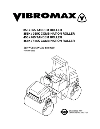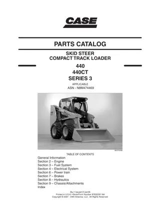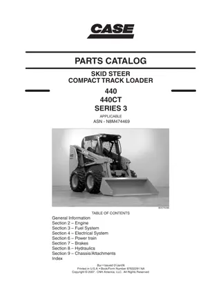
CASE 465 Skid Steer Loader Parts Catalogue Manual Instant Download
Please open the website below to get the complete manualnn// n
Download Presentation

Please find below an Image/Link to download the presentation.
The content on the website is provided AS IS for your information and personal use only. It may not be sold, licensed, or shared on other websites without obtaining consent from the author. Download presentation by click this link. If you encounter any issues during the download, it is possible that the publisher has removed the file from their server.
E N D
Presentation Transcript
??? ????? ????? ?????? ??????? ???????????? ????? ???????? ??????? ??? ???????? ??????????? ???? ????? ????????????? ??? ????????? ?????????? ????? ????? ?????? ??????? ?????????? ??? ???????? ?????? ??? ???????? ???????? ??????????? ???????? ?? ?? ?????? ???????? ?? ?? ????? ?????? ???????? ?? ?? ??????????? ?????? ???????? ?? ?? ??????? ?? ???????? ???????? ?? ?? ?????? ????? ???????? ?? ?? ?????? ???????? ?? ?? ?????????? ???????? ?? ?? ??????????????????? ????? ??????? ???????? ????????? ???????? ?? ??????? ??????? ?? ???? ???? ?????????
???? ????????? ???? ????????? ???? ?????? ??? ????? ????????????? ??? ??????? ??? ???????? ??? ??????????????? ??? ???? ????? ???????? ?????????? ???? ???????????????????????????????????????????????????? ???? ????? ?????? ??? ????? ???????????? ??? ???????? ??? ??????????? ???????????? ??????????? ???? ???????? ???? ????? ????????????? ?????????????? ??? ???? ??????????????????????????????????????????????????????????????????????????????????????????????????????????????????????????????? ????????? ??????? ????? ?????? ???? ??????????? ???????? ??????? ???????? ?????? ??????? ??????? ??? ????????? ? ??????? ??? ??????? ?? ???? ???? ??? ?????????? ??? ?????????? ???????? ??? ????????? ??????????? ???????? ???????? ???????? ??????????? ???? ???? ???????? ????? ? ???????? ??? ? ?????? ? ??????
TABLE OF CONTENTS 02-01 02-02 02-03 02-04 02-05 02-06 02-06A 02-07 02-07A 02-08 02-08A 02-09 02-10 02-11 02-12 02-13 02-14 02-15 02-16 02-17 02-18 02-19 02-20 02-20A 02-21 02-22 02-23 02-24 02-25 02-26 02-27 02-27A 02-28 02-29 02-30 02-31 02-32 02-33 02-34 02-35 02-36 02-37 03-01 03-02 03-03 03-04 03-05 03-06 03-07 03-08 03-09 03-10 RADIATOR - COOLANT RECOVERY SYSTEM FAN - FAN BELT EXHAUST SYSTEM ENGINE - AIR CLEANER GRID HEATER ENGINE - MOUNTING OIL FILL, ENGINE ENGINE - PUMP DRIVE (WITH SPLIT PUMP CONFIGURATION) ENGINE - PUMP DRIVE (WITH TANDEM PUMP CONFIGURATION) ENGINE ENGINE - BLOCK HEATER CYLINDER BLOCK CYLINDER BLOCK OIL PUMP, PAN CYLINDER BLOCK - COVERS CYLINDER BLOCK - COVERS CYLINDER BLOCK - COVERS BREATHER - ENGINE CYLINDER HEAD CYLINDER HEAD - COVERS CYLINDER HEAD - VALVE MECHANISM MANIFOLD - INTAKE MANIFOLD - EXHAUST TURBOCHARGER CRANKSHAFT PISTONS - CONNECTING ROD PISTONS - CONNECTING ROD FLYWHEEL - ENGINE PULLEY - CRANKSHAFT CAMSHAFT ENGINE, OIL TURBOCHARGER, PIPES AND CONNECTIONS OIL PUMP - ENGINE OIL FILTERS - ENGINE OIL FILTER AND COOLER WATER PUMP COOLING SYSTEM - ENGINE THERMOSTAT - ENGINE COOLING SYSTEM WATER PUMP - CONTROL FAN DRIVE POWER TAKE OFF ENGINE - LIFT HOOK FUEL LINES CONTROLS - THROTTLE FUEL INJECTION PUMP FUEL INJECTION SYSTEM FUEL INJECTION SYSTEM FUEL INJECTION SYSTEM FUEL FILTER FUEL PUMP FUEL INJECTION SYSTEM FUEL INJECTION SYSTEM
TABLE OF CONTENTS 04-01 04-02 04-03 04-04 04-05 04-06 04-07 04-09 04-11 04-12 04-13 04-14 04-15 04-15A 04-16 04-16A 04-17 04-18 04-19 04-20 06-01 06-01A 06-01B 06-02 06-03 06-04 06-05 06-05A 06-06 06-06A 06-07 06-08 06-09 06-10 06-11 06-12 06-13 06-14 06-15 06-16 06-17 06-17A 06-18 06-19 06-20 06-21 06-22 06-23 06-24 06-25 06-26 06-27 STARTER ALTERNATOR STARTER MOUNTING - ALTERNATOR MOUNTING BATTERY - CABLES DISCONNECT SWITCH - REMOTE JUMP START HARNESS, FRONT - CHASSIS HARNESS, REAR - CHASSIS SWITCH MOUNTING - CHASSIS OPTIONS HARNESS - CAB, SEAT BAR HARNESS - DOOR, FRONT HARNESS, FRONT - AUXILIARY WIPER, WINDSHIELD CONTROLS, RIGHT HAND - HANDLE CONTROLS, RIGHT HAND - HANDLE CONTROLS, LEFT HAND - HANDLE CONTROLS, LEFT HAND - HANDLE LAMP ASSY - BEACON, ROTATING HORN - MOUNTING BACKUP ALARM ELECTRICAL ACCESSORIES SOCKET HYDROSTATICS - PUMP, SUPPLY AND RETURN (SPLIT PUMP CONFIGURATION) PUMP, TANDEM - MOUNTING (TANDEM PUMP CONFIGURATION) HYDROSTATICS - PUMP, SUPPLY AND RETURN (TANDEM PUMP CONFIGURATION) OIL COOLER - MOUNTING OIL COOLER - MOUNTING (HIGH FLOW) HYDROSTATICS - CASE DRAIN HYDROSTATICS - DRIVE MOTORS (WITH SPLIT PUMP CONFIGURATION) HYDROSTATICS - DRIVE MOTORS (WITH TANDEM PUMP CONFIGURATION) HYDROSTATICS - TWO SPEED (SPLIT PUMP CONFIGURATION) HYDROSTATICS - TWO SPEED (TANDEM PUMP CONFIGURATION) HYDROSTATICS - TWO SPEED, VALVE ASSY FILTER ASSY - MOUNTING TANDEM PUMP TANDEM PUMP TANDEM PUMP TANDEM PUMP TANDEM PUMP TANDEM PUMP TANDEM PUMP TANDEM PUMP PUMP, GEAR PUMP, GEAR (TANDEM PUMP CONFIGURATION) PUMP, GEAR (HIGH FLOW) MOTOR ASSY - SINGLE SPEED MOTOR ASSY - SINGLE SPEED MOTOR ASSY - SINGLE SPEED MOTOR ASSY - TWO SPEED MOTOR ASSY - TWO SPEED MOTOR ASSY - TWO SPEED MOTOR ASSY - TWO SPEED MOTOR ASSY - TWO SPEED MOTOR ASSY - TWO SPEED
https://www.ebooklibonline.com Hello dear friend! Thank you very much for reading. Enter the link into your browser. The full manual is available for immediate download. https://www.ebooklibonline.com
TABLE OF CONTENTS 06-28 06-29 06-30 06-31 06-32 06-33 06-34 06-35 06-36 07-01 07-02 08-01 08-01A 08-02 08-02A 08-03 08-04 08-05 08-06 08-07 08-08 08-09 08-10 08-11 08-12 08-13 08-14 08-14A 08-15 08-16 08-17 08-18 08-19 08-20 09-01 09-02 09-04 09-05 09-06 09-06A 09-07 09-07A 09-07B 09-08 09-09 09-10 09-11 09-12 09-12A 09-13 09-14 09-15 PUMP, TANDEM (87350025) PUMP, TANDEM (87350025) PUMP, TANDEM (87350025) PUMP, TANDEM (87350025) PUMP, TANDEM (87350025) PUMP, TANDEM (87350025) AXLE ASSY DRIVE LINE WHEELS BRAKE SYSTEM - HYDRAULIC BRAKE SYSTEM - HYDRAULIC (WITH TANDEM PUMP CONFIGURATION) HYDRAULICS - LOADER LIFT (WITH SPLIT PUMP CONFIGURATION) HYDRAULICS - LOADER LIFT (WITH TANDEM PUMP CONFIGURATION) HYDRAULICS - LOADER BUCKET (WITH SPLIT PUMP CONFIGURATION) HYDRAULICS - LOADER BUCKET (WITH TANDEM PUMP CONFIGURATION) HYDRAULICS - SELF-LEVELING VALVE ASSY, SELF LEVEL HYDRAULICS - AUXILIARY SYSTEM HYDRAULICS - RIDE CONTROL HYDRAULICS - COUPLER SYSTEM VALVE ASSY, CONTROL - HIGH FLOW VALVE ASSY, CONTROL - LOADER VALVE ASSY, CONTROL - LOADER CYLINDER - LOADER LIFT CYLINDER - LOADER BUCKET HYDRAULIC ATTACHMENTS - CONTROLS HIGH FLOW (SPLIT PUMP CONFIGURATION) HIGH FLOW (TANDEM PUMP CONFIGURATION) COMBINATION VALVE - HIGH FLOW HIGH FLOW - AUXILIARY SYSTEM SECONDARY FRONT AUXILIARY SECONDARY FRONT AUXILIARY - VALVE ASSY SECONDARY FRONT AUXILIARY VALVE ASSY, CONTROL - HIGH FLOW FRAME - LOADER LIFT SUPPORT - LOADER FRAME COUPLER, MECHANICAL COUPLER, HYDRAULIC BUCKETS, LOADER - 1860 MM (73 IN) WIDE BUCKET BUCKETS, LOADER - 2083 MM (82 IN) WIDE BUCKET BUCKETS, LOADER - 2134 MM (84 IN) WIDE BUCKET BUCKET, CUTTING EDGE (BOLT-ON CUTTING EDGE) PALLET FORK CHASSIS PLATES, FLOOR CONSOLE, CONTROL CONTROLS - LOADER AND GROUND DRIVE LINKAGE - LOADER AND GROUND DRIVE (SPLIT PUMP CONFIGURATION) LINKAGE - LOADER AND GROUND DRIVE (TANDEM PUMP CONFIGURATION) LINKAGE - AUXILIARY SYSTEM HOOD DOOR, REAR
TABLE OF CONTENTS 09-16 09-17 09-18 09-19 09-19A 09-20 09-21 09-22 09-23 09-24 09-25 09-26 09-27 09-28 09-29 09-29A 09-30 09-31 09-33 09-34 09-35 09-36 09-37 09-38 09-38A 09-39 09-40 09-41 09-42 09-43 09-44 09-45 MAT, FLOOR COUNTERWEIGHTS SEAT, MOUNTING - NON-SUSPENSION SEAT, MOUNTING - SUSPENSION SEAT, MOUNTING - SUSPENSION, RETRACTABLE SEAT BELT SEAT - SUSPENSION SEAT - SUSPENSION SEAT - SUSPENSION FRAME AND SEAT BAR LIFT HOOK REAR LATCH AND PIVOT HEAT SHIELD HEADLINER DOOR, FRONT - WINDSHIELD DOOR, FRONT - MOUNTING, FRAME EXTENSION PANELS DOOR, FRONT - LATCH WINDOWS - SIDE AND TOP HEATER AND AIR CONDITIONING - MOUNTING HEATER AND AIR CONDITIONING - COMPRESSOR MOUNTING HEATER AND AIR CONDITIONING - RECEIVER-DRIER MOUNTING HEATER AND AIR CONDITIONING - HOSES HEATER AND AIR CONDITIONING - HEADLINER HEATER AND AIR CONDITIONING ASSY HEATER AND AIR CONDITIONING ASSY HEATER - MOUNTING HEATER HEATER ASSY DECALS DECALS DECALS - ENGLISH DECALS - BRAZILIAN PORTUGUESE, FRENCH CANADIAN, LATIN AMERICAN SPANISH
GENERAL INFORMATION PROPRIETARY NOTICE The contents of this manual are proprietary data of this company. Reproduction or use of any part for other than the operation and maintenance of our equipment is permissible only if expressly authorized in writing. Additional copies may be obtained from your dealer. Address requests for copies to your Dealer and refer to the publication part number appearing on the bottom of the rear catalog cover or on the title page. OWNER ASSISTANCE We want you to be completely satisfied with your investment. Normally any problems with your equipment will be handled by your dealer's Service Department; however, misunderstandings can occur. If your problem has not been handled to your satisfaction, we suggest the following: 1. Contact th e o wner or G eneral Manager of th e dealership, explain the problem, and request assistance. When additional assistance is needed, your dealer has direct access to our office. COMPANY POLICY Company policy, which is one of continuous improvement, reserves the right to change prices and to make changes in design and specification at any time without notice and without obligation to modify units previously built. All data given in this book is subject to production variations. Dimensions and weights are approximate only and the illustrations do not necessarily show machines in standard condition. For exact information about any particular machine please consult your dealer. 2. Provide your dealer with: Your Name, Address, and Telephone number Machine Model and Serial Number Dealership Name and Address Machine purchase date and amount of use Nature of problem Be aware that your problem will likely be resolved in the dealership using the dealer's facilities, equipment, and personnel. So it is important that your initial contact be with the dealer. PARTS AND ACCESSORIES Genuine parts and ac cessories have been specifically designed for these machines. We would like to point out that non-genuine parts and accessories have NOT been examined and released by the Company. The installation and or use of such products could have negative effects upon the design characteristics of your machine and thereby affect its safety. The company is not liable for any damage caused by the use of non-genuine parts and accessories. SPARE PARTS To maintain operating efficiency, use original spare parts. When ordering parts, give the following information: Machine Model Machine and Engine Serial Numbers Part Number from the Parts Catalog IMPROVEMENTS We are continually striving to improve our products. We reserve the right to make improvements or changes when it becomes practical and possible to do so, without incurring any obligation to make changes or additions to the equipment sold previously. MODEL CODES The range of machines listed may not be available in all countries or markets therefore, for the latest information consult your local dealer. I
HOW TO USE YOUR PARTS CATALOG 1. Figure Number 2. Sequence Code within the Figure Number 3. Page Number within the Sequence Code 4. Date of Printing (month / year) 5. Figure Description 6. General information regarding the figure 7. Parts supplied in repair kits per symbol reference 8. Figure call-out of the part number (REF) 9. Technical specifications relating to the part indicated 10. Figure call-out includes bracketed items, the included items may also be listed in the additional description area 11. Orientation - Arrow indicates front of the machine 12. Footnote - Additional information relating to the part number. In this example, 08-20 equals another figure that this part is shown on 13. Part Number NSS = Not Serviced Separately (Non-serviced parts) Bracketed numbers = not available as service parts in this market 14. Not Available as service part in this market 15. YR/SN Year Before 01/85 = Part valid for production January 1985 and before From 01/85 = Part valid for production from January 1985 and after BTW 01/85 & 02/02 = Part valid for machines produced between January 1985 and February 2002. Serial Number (P.I.N.) BSN JJC0268800 = Part valid for serial number JJC0268800 and below ASN JJC0268800 = Part valid for serial number JJC0268800 and above BTW JJC0178000 & JJC0179000 = Part valid for serial numbers between JJC0178000 & JJC0179000 16. Total Quantity of the Part referred to in the page. The quantity can be replaced by the following indications: AR = As Required X = As required 17. Part Description 18. Additional description of the part to help confirm identification 19. Figure Notes 20. Model Number(s) RIGHT-HAND AND LEFT-HAND DIMENSIONS The reference to right-hand and left-hand in this catalog is identified by the operator standing at the rear of the basic unit (without rear attachment), looking toward the front of the machine (in normal forward travel). Metric and U.S. hardware dimensions do not show the numeric designations of standard coarse threads. A number following a semi colon (;) is the class or grade of hardware. A comma (,) represents the decimal point (.) used in U.S. dimensions. For pages covering any machine attachments, right-hand and left-hand are defined by the operator sitting in the position for proper operation of the attachment. III
EXPLANATION OF ABBREVIATIONS AC adj amp AR Alternating Current adjustable ampere As required Serial number and after P.I.N. and after L lb lb-ft lg LH LH thd litre pounds pound-foot long left-hand left-hand thread ASN blkhd br bulkhead branch before Serial number before P.I.N. between M m ml mm (prefix) metric thread size metre milliliter millimetre BSN BTW NF No. NPT NS National Fine number National Pipe Thread National Super Fine cc cl cmprsn cn pt cp pt CRS CST cu yd cubic centimetre class compression cone point cup point Chrome Alloy Steel Carbon Steel cubic yard OD ohm Or ORB ORFS ov cntr ov pt oz outside diameter electrical unit of resistance O-ring O-ring boss O-ring face seal over center oval point ounce DC deg dg pt dia dr type Direct Current degree dog point diameter drive type P psi pt PT pitch pounds per square inch pint pipe thread fc fc sl fem fem PT fl flat pt ft face face seal female female pipe thread flare flat point feet or foot rd rd holes RH RH thd rpm round round holes right-hand right-hand thread revolutions per minute ga gal gpm gr gauge gallon or gallons gallons per minute grade sl sq SST st strk sw self-locking square Stainless Steel self-tapping stroke swivel hd hdg pt hp ID in Incl. inv fl head half dog point horsepower inside diameter inch or inches Includes inverted flare T thk tpr tube OD teeth thick taper tube outside diameter V W X yd volt or volts watt or watts as required yard K kg km/h kilo kilogram kilometers per hour IV
SECTION INDEX 02-01 02-02 02-03 02-04 02-05 02-06 02-06A 02-07 02-07A 02-08 02-08A 02-09 02-10 02-11 02-12 02-13 02-14 02-15 02-16 02-17 02-18 02-19 02-20 02-20A 02-21 02-22 02-23 02-24 02-25 02-26 02-27 02-27A 02-28 02-29 02-30 02-31 02-32 02-33 02-34 02-35 02-36 02-37 RADIATOR - COOLANT RECOVERY SYSTEM FAN - FAN BELT EXHAUST SYSTEM ENGINE - AIR CLEANER GRID HEATER ENGINE - MOUNTING OIL FILL, ENGINE ENGINE - PUMP DRIVE (WITH SPLIT PUMP CONFIGURATION) ENGINE - PUMP DRIVE (WITH TANDEM PUMP CONFIGURATION) ENGINE ENGINE - BLOCK HEATER CYLINDER BLOCK CYLINDER BLOCK OIL PUMP, PAN CYLINDER BLOCK - COVERS CYLINDER BLOCK - COVERS CYLINDER BLOCK - COVERS BREATHER - ENGINE CYLINDER HEAD CYLINDER HEAD - COVERS CYLINDER HEAD - VALVE MECHANISM MANIFOLD - INTAKE MANIFOLD - EXHAUST TURBOCHARGER CRANKSHAFT PISTONS - CONNECTING ROD PISTONS - CONNECTING ROD FLYWHEEL - ENGINE PULLEY - CRANKSHAFT CAMSHAFT ENGINE, OIL TURBOCHARGER, PIPES AND CONNECTIONS OIL PUMP - ENGINE OIL FILTERS - ENGINE OIL FILTER AND COOLER WATER PUMP COOLING SYSTEM - ENGINE THERMOSTAT - ENGINE COOLING SYSTEM WATER PUMP - CONTROL FAN DRIVE POWER TAKE OFF ENGINE - LIFT HOOK
02-01 p1 01/06 RADIATOR - COOLANT RECOVERY SYSTEM
02-01 p1 01/06 RADIATOR - COOLANT RECOVERY SYSTEM REF FN PART NUMBER YR/SN QTY DESCRIPTION 1 1A 1B 2 87013856 87032485 87032486 87020980 1 1 1 1 RADIATOR Incl. 1A, 1B FITTING Drain CAP, RADIATOR RESERVOIR, COOLANT EXPNSN Incl. Cap 257884A1 PLUG FRAME Upper Radiator; Com ponent Parts Not Serviced Separately; Replaces 87024337 BOLT Short NK, 1/4"-20 x 3/4", G5, Full Thd CUSHION HOSE Coolant Recovery WASHER, LOCK Belleville, M6 NUT 1/4"-20, G5 FRAME ASSY Lower Radiator SEAL CLAMP HOSE ASSY. Lower Radiator CLAMP HOSE ASSY. Upper Radiator PIN, SPLIT (COTTER) WASHER M10 x 20 x 2 257884A1 87459340 1 1 3 4 5 6 7 8 9 10 11 12 13 14 15 16 280638 87017045 87023941 322357 7770 87436062 87033635 86050202 87037868 86625031 87040170 216698 895-11010 4 4 1 4 4 1 4 3 1 1 1 2 2 465
02-02 p1 02/06 FAN - FAN BELT
02-02 p1 02/06 FAN - FAN BELT REF FN PART NUMBER YR/SN QTY DESCRIPTION 1 1 2 3 4 5 5 6 87025470 238344A1 A184545 140045 814-10070 87046890 87461514 434-612 1 1 1 4 4 1 1 4 FAN 480 m m ; If Used FAN 518 m m ; If Used SPACER WASHER, LOCK BOLT Hex, M10 x 70, 8.8 SHROUD ASSY. Used With 480 m m Fan; If Used SHROUD ASSY. Used With 518 m m Fan; If Used BOLT, CARRIAGE Short NK, 3/8"-16 x 3/4", G5, Full Thd SCREW Hex, M8 x 20, 8.8 WASHER, LOCK Belleville, M8 WASHER M8 x 16 x 1.6 GUARD Fan V-BELT Fan Belt 7 8 9 10 11 120104 322358 86624184 87046887 86982450 3 3 3 1 1 465
02-03 p1 02/06 EXHAUST SYSTEM
02-03 p1 02/06 EXHAUST SYSTEM REF FN PART NUMBER YR/SN QTY DESCRIPTION 1 2 3 4 5 6 7 8 9 10 11 11 12 13 14 15 16 17 18 19 20 21 22 23 24 25 26 27 87035578 9706717 140046 87034631 411345A1 43139 86608204 43130 87034630 140045 A13240 87461995 87040074 87033361 43130 322358 814-8045 86625263 256690A1 87029961 614-8030 86633393 86606073 304811A1 43127 247026A1 832-41408 895-15008 1 1 1 1 3 3 1 1 1 1 1 1 1 1 1 4 2 3 3 1 1 1 1 1 3 1 3 8 MUFFLER Assy SCREW Hex, M12 x 70, 8.8, Full Thd WASHER, LOCK Belleville, M12 ROD Muffler Support NUT M10 SCREW Hex, M10 x 25, 8.8, Full Thd SPACER SCREW Hex, M8 x 50, 8.8 ROD Muffler Support WASHER, LOCK CLAMP Muffler CLAMP Muffler; Replaces A13240 TUBE Tail Pipe ROD Muffler Support SCREW Hex, M8 x 50, 8.8 WASHER, LOCK Belleville, M8 BOLT Hex, M8 x 45, 8.8 WASHER M8 x 20 x 1.6 SPACER ROD Muffler Support BOLT Hex, M8 x 30, 8.8 SPACER Hose Clam p GASKET TUBE Exhaust Extension BOLT Hex, M8 x 25, 8.8 PLATE, LARGE Exhaust Doubler NUT M8 x 1.25", Cl 8 WASHER M8 x 20 x 1.6 465
02-04 p1 01/06 ENGINE - AIR CLEANER
02-04 p1 01/06 ENGINE - AIR CLEANER REF FN PART NUMBER YR/SN QTY DESCRIPTION 1 2 3 4 5 6 8 7 8 9 10 10 11 12 13 13 14 87036648 87037984 87037985 87046722 120100 9824259 322358 614-8030 322358 214-1416 87046614 87352019 214-1460 214-1448 87046613 87352003 825-1408 1 1 1 1 4 4 3 4 3 2 1 1 1 1 1 1 2 FILTER, AIR Incl. 2, 3 ELEMENT Powercore ELEMENT BRACKET BOLT Hex, M6 x 20, 8.8 WASHER M6 x 12 x 1.6 WASHER, LOCK Belleville, M8 BOLT Hex, M8 x 30, 8.8 WASHER, LOCK Belleville, M8 CLAMP Type F #16 HOSE HOSE Replaces 87046614 CLAMP Type F #60 CLAMP Type F #48 HOSE Air Cleaner HOSE Air Cleaner; Replaces 87046613 NUT M8, Cl 8 465
02-05 p1 04/05 GRID HEATER
02-05 p1 04/05 GRID HEATER REF FN PART NUMBER YR/SN QTY DESCRIPTION 1 2 3 4 5 6 7 8 9 10 11 12 13 14 15 16 7770 43151 80681 80684 80701 87825 88146 140046 322357 9626568 82017872 86014151 86625038 87030820 87406968 87047862 L18331 2 2 2 1 2 1 2 2 2 2 1 2 2 1 1 1 1 NUT 1/4 SCREW M12 x 20 WASHER, LOCK 5/16" WASHER, LOCK #10 WASHER 1/4 NUT No. 10 BOLT 1/4 x 1 WASHER, LOCK M12 WASHER, LOCK Belleville, M6 NUT 5/16 HEATER Grid GASKET CLAMP 25.4 m m CABLE Grid Heater SWITCH, SOLENOID CABLE Grid Heater STRAP 465
02-06 p1 01/06 ENGINE - MOUNTING
02-06 p1 01/06 ENGINE - MOUNTING REF FN PART NUMBER YR/SN QTY DESCRIPTION 1 2 3 4 5 6 7 8 9 10 11 87039487 REF 86982450 412085 412066 140046 87041763 A140221 87032338 350616 390350A1 1 1 1 4 1 4 1 3 6 3 2 ENGINE Engine Assy INSTRUCTION Rem ote Oil Fill; See Figure 02-06A V-BELT SCREW Hex, M12 x 80, 10.9 NUT, LOCK M16 x 2, Cl 8 WASHER, LOCK Belleville, M12 MOUNT, ENGINE MOUNTING PARTS WASHER, LOCK .656 x 2 x .188 in SCREW Hex, M16 x 90, 8.8 PLATE 465
02-06A p1 04/05 OIL FILL, ENGINE
02-06A p1 04/05 OIL FILL, ENGINE REF FN PART NUMBER YR/SN QTY DESCRIPTION 1 2 3 4 5 6 6A 7 8 9 10 11 12 13 14 15 614-12025 892-11012 214-1704 14458781 281-54810 87050090 87458899 87432267 87432275 87434315 87434316 87434317 87434847 87438418 87445427 L18331 2 2 1 1 2 1 1 1 2 1 1 1 1 1 1 1 BOLT M12 x 25 WASHER, LOCK 12 m m CLAMP Type M #4 O-RING 1-9/16 x 1-3/4 SCREW 5/16-18 x 5/8 TUBE ASSY. Oil Fill; If Used SUPPORT Oil Fill; If Used TUBE Oil Fill SPRING 35 m m DIPSTICK HOSE ASSY. Oil Fill HOSE ASSY. Oil Fill ANGLE Oil Fill Mounting TUBE Oil Guage CAP, FILLER STRAP 465
02-07 p1 02/06 ENGINE - PUMP DRIVE (WITH SPLIT PUMP CONFIGURATION)
02-07 p1 02/06 ENGINE - PUMP DRIVE (WITH SPLIT PUMP CONFIGURATION) REF FN PART NUMBER YR/SN QTY DESCRIPTION REF INSTRUCTION MODELS WITH SPLIT PUMP CONFIGURATION ENGINE SPACER Used With Ref 5, 7 SPACER Used With Ref 5A, 7A BOLT Hex, M8 x 30, 10.9 WASHER, LOCK Belleville, M8 BOX Splitter; Used With Ref 2, 7 BOX Splitter; Used With Ref 2A, 7A SCREW Hex Soc Hd, M10 x 70, 12.9 SEAL PROTECTION Used With Ref 2, 5 SEAL Used With Ref 2A, 5A GEAR 29T GEAR Pum p Drive RING, SNAP #93, Ext SCREW Hex Soc Hd, M10 x 40, 8.8 CAP Splitter Box BREATHER Air Vent BUSHING 3/4 To 1/8 FITTING 3/4 NPTF Male x 3/4 NPTF Fem ale INDICATOR Oil; If Used TUBE Dipstick; If Used PLUG 1/4 10 BOLT Hex, M10 x 80, 8.8 10 WASHER, LOCK 1 BRACKET Oil Dipstick Bracket; If Used 1 SCREW Hex, M10 x 20, 8.8, Full Thd 1 WASHER, LOCK M10 x 20 x 2 1 CLAMP 9.5 m m M12 Bolt 1 NUT M10, Flg Ser 1 2 2A 3 4 5 5A 6 7 7A 8 9 10 11 12 13 14 15 16 17 18 19 20 21 22 23 24 25 87039487 87049924 87462294 43235 322358 87053351 87462295 863-10070 9790499 87462383 9701486 87051053 271877 864-10040 87053352 46566 88873 217-1020 9635238 86606076 217-504 814-10080 140045 87462692 43138 140017 515-2595 43435 1 1 1 6 6 1 1 2 1 1 2 1 4 8 1 1 1 1 1 1 1 465
Suggest: If the above button click is invalid. Please download this document first, and then click the above link to download the complete manual. Thank you so much for reading
02-07A p1 01/06 ENGINE - PUMP DRIVE (WITH TANDEM PUMP CONFIGURATION)
https://www.ebooklibonline.com Hello dear friend! Thank you very much for reading. Enter the link into your browser. The full manual is available for immediate download. https://www.ebooklibonline.com


