Advanced DS-SSS Acquisition Methods Explored
Learn about the efficient acquisition methods for DS-SSS signals using serial search, parallel search, and sequential estimation. Understand the correlation techniques, synch indicators, and how the process reduces acquisition time effectively.

Download Presentation

Please find below an Image/Link to download the presentation.
The content on the website is provided AS IS for your information and personal use only. It may not be sold, licensed, or shared on other websites without obtaining consent from the author. Download presentation by click this link. If you encounter any issues during the download, it is possible that the publisher has removed the file from their server.
E N D
Presentation Transcript
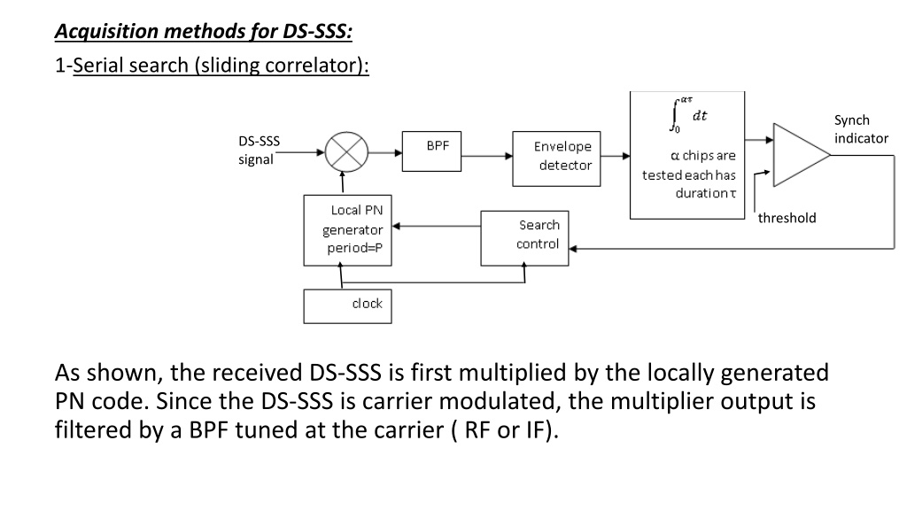
Acquisition methods for DS-SSS: 1-Serial search (sliding correlator): Synch indicator DS-SSS signal threshold As shown, the received DS-SSS is first multiplied by the locally generated PN code. Since the DS-SSS is carrier modulated, the multiplier output is filtered by a BPF tuned at the carrier ( RF or IF).
The envelope detector will detect the energy of the carrier and then accumulated by an accumulator ( integrator ) for PN chips (this is a partial correlation since <P). Now, if the received DS-SSS is synchronized with the locally generated PN generator, the correlator ( multiply & accumulate) will give high value greater than a pre-set threshold. Otherwise, the correlator output will be low, and the search control will step (shift) the phase of the local PN generator by one chip and the same process will be repeated until the correct phase of the local code generator is achieved. Of course, this will take at most the whole period and in each time chips are tested. i.e,the worst case acquisition time will be P. ( The actual acquisition time is less than this depending on the random initial phase between the received and the local codes).
c(t) 2-Parallel search c(t-0.5 ) DS-SSS signal Synch control c(t- ) c(t-(P-1) ) The serial search has large acquisition time specially if the period of the code is so long and is made large to reduce the sidelobes of the partial correlation.
Instead of using the serial search, a parallel is used. Here, we need two times the period of correlators to check all the possible phases of the code with time accuracy of 0.5 (half of chip duration). The acquisition time is reduced to which is the correlation time of one correlator. The receiver must generate a local code c(t) plus all possible phases with time shifts of 0.5 . This is usually done by special techniques from the same feedback shift register. The main disadvantage of the parallel search is its high complexity 3-Sequential Estimation: This works only at baseband. Hence the DS- SSS must be first BPSK carrier demodulated to obtain the original transmitted code c(t) plus noise n(t). Then applied to system shown.
C(t)+n(t) S 2 1 Synch indication threshold Switch S is first at position 1 to load n bits serially to the shift register. Then S is changed to position 2 to close the loop of the shift register and generate the locally generated code. Meanwhile, the received noisy code is correlated with the locally generated code using chips(partial correlation).
If the received n bits loaded to the register are correct, then the correct phase is acquired, and the synch indicator will give +ve reading (exceeding the threshold). Otherwise, S will be put at position 1 again to reload another n bits in a hope that they are correct. For error free case, the acquisition time is (n+ ) which is the time for loading n correct bits and checking them by the correlator with chips being tested. It should be noted, however, that this method will give correct acquisition only at high and moderate signal to noise ratio where the BPSK demodulator can work and give correct received bits. Tracking Methods for DS-SSS : Once acquisition or coarse synchronization has been accomplished, tracking or fine synchronization takes place. Specifically, this must include chip synchronization and for coherent systems, carrier phase locking. In many practical systems, no data are transmitted for a specified time, sufficiently long to ensure that acquisition has occurred. The basic tracking loops for DS-SSS are:
1-Delay Locked Loop (DLL): As shown in the figure, the received DS-SSS is multiplied by two locally generated PN sequences delayed from each other by one chip . The BPF tuned at RF (or IF) is designed to have a bandwidth of twice the data rate. To data demodulator c(t+ ) DS-SSS signal c(t+ +0.5 ) - E1 Y E2 + c(t+ -0.5 )
The outputs of each envelope detectors E1and E2are approximately given by: ?1,2 |? ? ? ? + 0.5? | = Rcc( 0.5 )| where E1= Rcc( + 0.5 ) and E2= Rcc( - 0.5 ) Where Rcc(x) is the autocorrelation of the code c(t). The output of the adder Y(t)= E2 E1is plotted below: We see from this figure that when is +ve, a +ve voltage proportional to Y instructs the VCO to increase its frequency, thereby forcing to decrease, while when is -ve, a -ve voltage proportional to Y instructs the VCO to reduce its frequency thereby forcing to increase towards zero. Rcc( - 0.5 ) Y - -Rcc( + 0.5 )
When the tracking time error is made zero, an output of the local PN generator c(t+ )=c(t) which is correlated with received DS-SSS, giving c2(t)d(t)cos(w0t)=d(t)cos(w0t) which is a despreading narrow band passband signal that be demodulated by any conventional BPSK demodulator . Tau-dither loop (TDL):This is an alternate technique for tracking of DS-SSS. This loop is a DLL with a single arm as shown below: ?(?) gbipolar DS-SSS Ed(t) Ef(t) Y Vp(t) ?(?) ?(?) gbipolar c(t+ +0.5 ) vc(t) c(t+ -0.5 ) ?(?)
The control signals ? ? , ? ? and gbipolarare used to generate both arms of the DLL even though only one arm is present. The TDL is used in stead of DLL due to its simplicity. The operation of the TDL is explained by observing that the control waveforms generate the signal: ??? = ? ? c(t+ - 0.5 ) + ?(?)c(t + + 0.5 ) Note that, either one or the other, but not both, of these waveforms occurs at each instant of time. This vp(t) then multiplies the incoming DS-SSS [c(t) d(t) cos(wot)]. The output of the BPF is therefore: ??= ? ? ? ? ? ? c t + + 0.5 Whereas before in DLL the average occurs due to the BPF. The data are eliminated by the envelope detector to give: ??= ? ? ??? + 0.5 The input Y(t) to the loop filter is: ? ? = ??? gbipolar= ? ? ??? 0.5 The - ' sign was introduced by the inversion caused by gbiploar. Since each term is zero half of the time, the voltage into the VCO clock is as before in DLL : ??? = ??? 0.5 + ? ? ? ? c t c t + 0.5 + ? ? |???( 0.5 | ? ? |??? + 0.5 | |??? + 0.5 |


")

+n(t)")

:")