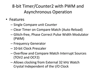
ARM Cortex-M Interrupt and Exception Programming Overview
Explore the fundamentals of interrupts and exceptions programming in ARM Cortex-M microcontrollers. Topics include interrupt handling mechanisms, interrupt vector table, interrupt priorities, control registers, and transitioning from reset to boot programs. Gain insights into the privileged execution modes and processor modes in ARM Cortex-M processors.

Download Presentation

Please find below an Image/Link to download the presentation.
The content on the website is provided AS IS for your information and personal use only. It may not be sold, licensed, or shared on other websites without obtaining consent from the author. Download presentation by click this link. If you encounter any issues during the download, it is possible that the publisher has removed the file from their server.
E N D
Presentation Transcript
Chapter 6 Interrupt and Exception Programming 1
Interrupt Vector Table for ARM Cortex-M Interrupt # Interrupt Memory Location (Hex) 0x00000000 0x00000004 0x00000008 0x0000000C 0x00000010 0x00000014 0x00000018 Stack Pointer initial value Reset NMI Hard Fault Memory Management Fault Bus Fault 1 2 3 4 5 6 Usage Fault (undefined instructions, divide by zero, unaligned memory access,...) Reserved Reserved Reserved Reserved SVCall Debug Monitor Reserved PendSV SysTick IRQ 0 for peripherals IRQ 1 for peripherals IRQ 239 for peripherals 7 8 9 10 11 12 13 14 15 16 17 255 0x0000001C 0x00000020 0x00000024 0x00000028 0x0000002C 0x00000030 0x00000034 0x00000038 0x0000003C 0x00000040 0x00000044 0x000003FC 4
Interrupt Priority for ARM Cortex-M Interrupt # 0 1 2 3 4 5 6 Interrupt Priority Level Stack Pointer initial value Reset NMI Hard Fault Memory Management Fault Bus Fault -3 Highest -2 -1 Programmable Programmable Programmable Usage Fault (undefined instructions, divide by zero, unaligned memory access,....) Reserved Reserved Reserved Reserved SVCall Debug Monitor Reserved PendSV SysTick IRQ 0 for peripherals IRQ 1 for peripherals IRQ 239 for peripherals 7 8 9 10 11 12 13 14 15 16 17 255 Programmable Programmable Programmable Programmable Programmable Programmable Programmable Programmable Programmable Programmable Programmable Programmable Programmable 8
CONTROL Register in ARM Cortex-M4 nPRIV (Privilege): 0: 1: Active Stack Pointer (ASP): 0: 1: Floating Point Context Active (FPCA) 0: No floating point context active. 1: Floating point context active. Defines the Thread mode privilege level Privileged Unprivileged Defines the currently active stack pointer (ASP = SPSEL) MSP is the current stack pointer. PSP is the current stack pointer. 9
Privileged level Execution and Processor Modes in ARM Cortex-M Processor Mode Thread Software Applications Privilege level Privileged and Unprivileged Always Privileged Handler ISR for Exceptions and IRQs In Thread mode, use bit 0 of the CONTROL register to select Privileged or Unprivileged 10
Processor Modes and Stack Usage in ARM Cortex-M Processor Mode Thread Handler Note: In Thread mode, use bit 1 of the Control register to select MSP or PSP for stack pointer. Software Applications Stack Usage MSP or PSP MSP ISR for Exceptions and IRQs 11
Processor Mode, Privilege, and Stack in ARM Cortex Mode Handler Handler Privilege Privileged Unprivileged Stack Pointer Main Any Typical Example usage Exception Handling Reserved since Handler is always Privileged Operating system kernel Thread Thread Thread Thread Privileged Privileged Unprivileged Unprivileged Main Process Main Process Application threads 12
Special function registers of ARM Cortex-M Register name MSP (main stack pointer) PSP (processor stack pointer) Privilege Usage Privileged Privileged or Unprivileged Privileged Privileged or Unprivileged Privileged Privileged Privileged Privileged Privileged Privileged PSR (Processor status register) APSR (application processor status register) ISPR (interrupt processor status register) EPSR (execution processor status register) PRIMASK (Priority Mask register) FAULTMASK(fault mask register) BASEPRI (base priority register) CONTROL (control register) Note: We must use MSR and MRS instructions to access the above registers 14
IRQ assignment in MSP432P401R INT# 1-15 16 17 18 19 20 21 22 23 24 25 26 27 28 IRQ# None 0 1 2 3 4 5 6 7 8 9 10 11 12 Vector location 0000 0000 to 0000 003C 0000 0040 0000 0044 0000 0048 0000 004C 0000 0050 0000 0054 0000 0058 0000 005C 0000 0060 0000 0064 0000 0068 0000 006C 0000 0070 Device CPU Exception(set by ARM) PSS CS PCM WDT_A FPU_INT Flash Controller COMP_E1 COMP_E2 TIMERA0 TIMERA0 TIMERA1 TIMERA1 TIMERA2 15
IRQ assignment in MSP432P401R (Cont.) INT# 29 30 31 32 33 34 35 36 37 38 39 40 41 42 IRQ# 13 14 15 16 17 18 19 20 21 22 23 24 25 26 Vector location 0000 0074 0000 0078 0000 007C 0000 0080 0000 0084 0000 0088 0000 008C 0000 0090 0000 0094 0000 0098 0000 009C 0000 00A0 0000 00A4 0000 00A8 Device TIMERA2 TIMERA3 TIMERA3 eUSCI_A0 eUSCI_A1 eUSCI_A2 eUSCI_A3 eUSCI_B0 eUSCI_B1 eUSCI_B3 eUSCI_B4 ADC14 TIMER32_INT1 TIMER32_INT2 16
IRQ assignment in MSP432P401R (Cont.) INT# 43 44 45 46 47 48 49 50 51 52 53 54 55 56 57-79 IRQ# 27 28 29 30 31 32 33 34 35 36 37 38 39 40 41-63 Vector location 0000 00AC 0000 00B0 0000 00B4 0000 00B8 0000-00BC 0000 00C0 0000 00C4 0000 00C8 0000-00CC 0000 00D0 0000 00D4 0000 00D8 0000-00DC 0000 00E0 0000 00E4 0000 013C Device TIMER32_INTC AES256 RTC_C DMA_ERR DMA_INT3 DMA_INT2 DMA_INT1 DMA_INT0 I/O Port P1 I/O Port P2 I/O Port P3 I/O Port P4 I/O Port P5 I/O Port P6 reserved 17
UCAxIE (UARTx Interrupt Enable) register Field UCTXCPTIE Bit D3 Description Transmit complete interrupt enable 0 = Interrupt disabled 1 = Interrupt enabled Start bit interrupt enable 0 = Interrupt disabled 1 = Interrupt Transmit interrupt enable 0 = Interrupt disabled 1 = Interrupt enabled Receive interrupt enable 0 = Interrupt disabled 1 = Interrupt enabled UCSTTIE D2 UCTXIE D1 UCRXIE D0 25
IE (Interrupt Enable) bit (d5) in T32CONTROLx (T32 Control) register 29


")
")


")
")


 register")

")

 bit (d5) in T32CONTROLx")