Understanding the Watchdog Timer in Embedded Systems
Explore the purposes and modes of the watchdog timer, learn how to activate and program it in interval timer mode, and understand the process of disabling it using predefined passwords. Discover the importance of the watchdog timer in recovering from software errors, conflicts between software and hardware states, and more.

Download Presentation

Please find below an Image/Link to download the presentation.
The content on the website is provided AS IS for your information and personal use only. It may not be sold, licensed, or shared on other websites without obtaining consent from the author. Download presentation by click this link. If you encounter any issues during the download, it is possible that the publisher has removed the file from their server.
E N D
Presentation Transcript
ECE 3567 ECE 3567 Lab 9 Lab 9 The Watchdog Timer The Watchdog Timer Dr. Gregg J Chapman Spring 2022 1
Purpose of the Watchdog Timer Purpose of the Watchdog Timer Recover from software operational error Conflicts between software and hardware state Software errors or algorithm failure. No response from a hardware device or user entry. Defective Memory Overheating Can use associated Watchdog Interrupt with a recovery plan of action.
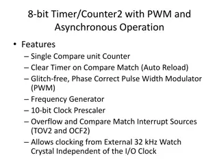
Other Useful Watchdog Timer Modes Other Useful Watchdog Timer Modes Power supply brown-out detection. (Supplies fall out of regulation) Periodic action of a parallel process (Interval Mode) Limited periodic timer with interrupt for parallel process
Lab Overview Lab Overview Activate the default Watchdog Timer. Program Watchdog Timer for different places in code. Use the Watchdog Timer in Interval Timer mode.
The Watchdog Timer The Watchdog Timer
Disabling The Watchdog Timer Disabling The Watchdog Timer // Disable Watchdog Timer // TI macro stops the watchdog WDT_A_hold(WDT_A_BASE); // Watchdog control register is configured using predefined password and hold bit using ORing WDTCTL = WDTPW|WDTHOLD; // Watchdog control register is configured directly with Magic Number WDTCTL =0x5A80;
The Watchdog Timer The Watchdog Timer Watchdog timer must be in hold to configure To set-up the watchdog timer we need to set WDTCTL register. Bits 15-8 of the WDTCTL must ALWAYS contain the password which is 5Ah. Writing anything else to these bits resets the MCU MSP430FR6989 User's Guide, page 634
Power Management Module Brown-Out Reset (BOR) Hardware 1.8 3.3 V Power-On Reset (POR) BOR or Software Power-Up Clear (PUC) Reconfigures Everything to Default
Clock Selection Following a PUC, the Watchdog timer must be HALTED, reconfigured, or refreshed within 32 milliseconds to avoid another PUC Reset.
Duplicating Lab 2 (with 100 mS ISR)
Lab 9 Re Lab 9 Re- -uses code from Lab 2 uses code from Lab 2 #include <driverlib.h> #include "stdio.h" #include "string.h" #include "ECE3567.h" /******************************** Variables *************************************/ volatileunsignedint ISR_Counter; volatileunsignedint ISR_Flag; volatileunsignedint ISR_Flag_10; intmain(void) { WDT_A_hold(__MSP430_BASEADDRESS_WDT_A__); //****** Stop the watchdog timer PMM_unlockLPM5(); //****** Disable power-on default mode Init_GPIO(); // Configure GPIO for LEDs Init_Timer_A0(); // Set-up TA0 for 100 mSec ISR __enable_interrupt(); while(1) // Main Loop { if(ISR_Flag == 1) // Single ISR { ISR_Flag = 0; // Reset flag } /************************** Interrupt Service Routine for Timer A0 ****************/ #pragma vector=TIMER0_A0_VECTOR __interrupt voidTimer_A(void) { ISR_Flag = 1; // 100 millisecond ISR ISR_Counter++; // Count ISRs if(ISR_Counter>=10) // 10 ISRs = 1 Sec. { ISR_Flag_10 = 1; // 1 Second to main ISR_Counter=0; // Reset Counter } return; } /****************************** END OF CODE ****************************************/ if(ISR_Flag_10 == 1) // 10 ISRs are 1 Second { P1OUT ^= BIT0; // Toggle RED LED P9OUT ^= BIT7; // Toggle GREEN LED ISR_Flag_10 = 0; // Dismiss } } } /********************************* END MAIN ***************************************/
Checkpoint 1: Checkpoint 1: Download & Run the Code Download & Run the Code 1. Download Lab9 Part 1 from the web site. 2. Create a new project Lab9A and copy the downloaded .c and .h files into your project. 3. Run the code without edits What to expect: When you run the code you will see the red and green LEDs will alternate continuously at 1 Hz, just as in Lab 2. Note that Timer_A0 is used for a 100 millisecond interrupt.
Checkpoint 2: Checkpoint 2: Observe the default setting of the WDT Observe the default setting of the WDT Until this lab the watchdog timer was disabled by: WDT_A_hold(__MSP430_BASEADDRESS_WDT_A__); 1. Comment out or delete this code line to observe behavior of WDT. What to expect: When you run the code you should see the RED LED is lit continuously. Because WDT is not cleared, it restarts the code periodically, every 32 milliseconds.
TI Watchdog Macros TI Watchdog Macros WDT_A_hold(__MSP430_BASEADDRESS_WDT_A__); // Sets WDTHOLD = 1 WDT_A_start(__MSP430_BASEADDRESS_WDT_A__); // Sets WDTHOLD = 0 WDT_A_resetTimer(__MSP430_BASEADDRESS_WDT_A__); // Sets WDTCNTCL = 1 to clear the WDT counter.
Procedure Procedure Part 1 Part 1 Add Code to: 1. HOLD the Watchdog Timer 2. Configure the Watchdog Timer for: a. The Password b. Keep the timer stopped c. Use ACLK d. Watchdog mode e. Clear the Watchdog count f. Set the Watchdog timeout interval (NOTE: This will change with each of 4 test cases) 3. Start the Watchdog Timer What to expect: For each case, the red LED will remain on if the Watchdog Timer resets the MCU. The red and green LEDs will alternate continuously with 1 second interval if the watchdog is reset before it times out.
Part 1 Code (main.c) #include <driverlib.h> #include "stdio.h" #include "string.h" #include "ECE3567.h" /******************************** Variables *************************************/ volatileunsignedint ISR_Counter; volatileunsignedint ISR_Flag; volatileunsignedint ISR_Flag_10; intmain(void) { WDT_A_hold(__MSP430_BASEADDRESS_WDT_A__); //****** Stop the watchdog timer PMM_unlockLPM5(); //****** Disable power-on default mode Init_GPIO(); // Configure GPIO for LEDs Init_Timer_A0(); // Set-up TA0 for 100 mSec ISR // Configure the Watchdog Timer here // Start the Watchdog Timer here WDT_A_start(__MSP430_BASEADDRESS_WDT_A__); __enable_interrupt(); while(1) // Main Loop { // Case 1 Watchdog Reset if(ISR_Flag == 1) // Single ISR { // Case 2 Watchdog Reset ISR_Flag = 0; // Reset } /************************* Interrupt Service Routine for Timer A0 ****************/ #pragma vector=TIMER0_A0_VECTOR __interrupt voidTimer_A(void) { // Case 4 Watchdog Reset ISR_Flag = 1; // 100 millisecond ISR ISR_Counter++; // Count ISRs if(ISR_Counter>=10) // 10 ISRs = 1 Sec. { ISR_Flag_10 = 1; // 1 Second to main ISR_Counter=0; // Reset Counter } return; } /******************************* END OF ISR *************************************/ /******************************* END OF CODE ************************************/ if(ISR_Flag_10 == 1) // 10 ISRs are 1 Second { // Case 3 Watchdog Reset P1OUT ^= BIT0; // Toggle RED LED P9OUT ^= BIT7; // Toggle GREEN LED ISR_Flag_10 = 0; // Dismiss } } } /********************************* END MAIN ***************************************/
Test Cases: Test Cases: 1. Reset the watchdog just inside the main while(1) loop. 2. Reset the watchdog inside the 100 millisecond loop: if(ISR_Flag == 1) 3. Reset the watchdog inside the 1 second loop: if(ISR_Flag_10 == 1) 4. Reset the watchdog inside the Timer_A0 Interrupt Service Routine. For each case document the WDTCTL register value that shortest Watchdog Timer Interval selection (WDTIS field) that will prevent the watchdog from resetting the MCU. BE SURE TO INCLUDE THE INTERVAL SELECTION FOR EACH CASE IN YOUR CODE COMMENTS! (Include all 4 final values and just comment out the ones not currently used)
Checkpoint 3 Checkpoint 3 Use the Watchdog Timer in Watchdog Timer Mode Use the Watchdog Timer in Watchdog Timer Mode Show case 4 (WDT reset in Timer A0 ISR) with the LEDs alternating to the Lab Monitors or GTA. Also show them the WDTCTL value that you selected for the shortest watchdog interval that did NOT reset the MCU. Does your selection make sense based on where you reset the WDT in the code?
Part 2 Code (main.c) #include <driverlib.h> #include "stdio.h" #include "string.h" #include "ECE3567.h" /******************************** Variables *************************************/ volatileunsignedchar ISR_Flag_WDT = 0; // Flag to tell main() that a WDT interrupt occurred /*************************** Function Prototypes *******************************/ // Consider placing function prototypes in a header file, e.g. ECE3567.h /***************************** First Function***********************************/ intmain(void) { WDT_A_hold(WDT_A_BASE); // Disable Watchdog counter PMM_unlockLPM5(); // Release pins from all input state Init_GPIO(); // Configure GPIO for LEDs // Configure WDTCTL - Password/WDT OFF/ ACLK/ Internal Mode / 1 Second count // Enable WDT interrupt // Start the Watchdog Timer __enable_interrupt(); while(1) // Main Loop { if(ISR_Flag_WDT == 1) // WDT ISR at 1 Second { P1OUT ^= BIT0; // Toggle RED LED P9OUT ^= BIT7; // Toggle GREEN LED ISR_Flag_WDT = 0; // Clear ISR flag } } } /********************************* END MAIN ***************************************/ /******************************** Interrupt Service Routine for WDT ****************/ //Your code goes here #pragma vector= __interrupt { // Flag to main return; } /****************************** END OF CODE ****************************************/
Procedure Procedure Part 2 Part 2 Download Lab9 Part 2 from the web site. Create a new project Lab9B and copy the downloaded .c and .h files into your project. Implement the alternating LEDs with WDT Interval Timer Mode: Initialize the watchdog timer with ACLK and clock divider for a 1 second timeout. You are expected to calculate a single hex number for WDTCTL register. Enable WDT Interrupt. Write WDT Interrupt service routine. As a function name use watchdog_timer . In the WDT ISR set ISR_Flag_WDT to 1 . Comment out the WDT_VECTOR #pragma in unused_interrupts.c What to expect: Red and green LEDs will alternate continuously with 1 second interval.
Watchdog Timer Initialization for Interval Timer Mode Watchdog Timer Initialization for Interval Timer Mode Change the WDTCTL value to do the following: Set password by changing WDTPW fields (Bit 15-8) 5Ah in WDTCTL register. Keep the top the Watchdog Timer stopped for now Choose the clock source as ACLK(32.768kHz) by changing WDTSSEL field. Select interval timer mode by changing WDTTMSEL field. Clear watchdog timer counter by setting WDTCNTCL. Select clock divider as Watchdog clock source/215 by setting WDTIS field properly to achieve 1 second intervals.
Checkpoint 4 Checkpoint 4 Use the Watchdog Timer in Interval Timer Mode Use the Watchdog Timer in Interval Timer Mode Show your circuit with the LEDs alternating to the Lab Monitors or GTA. Also show them the WDTCTL value that you used to configure the Watchdog for a 1 second ISR in Interval Mode.


")


")