Understanding Magnetism and Inductance in Physics
Explore the concepts of magnetism, inductance, and inductors in physics, including circuit diagram symbols, energy storage, calculations in RL circuits, and determining inductance. Learn about the differences between inductors and capacitors, as well as the properties and applications of solenoids. Discover the relationship between current, flux, and voltage in inductors.

Download Presentation

Please find below an Image/Link to download the presentation.
The content on the website is provided AS IS for your information and personal use only. It may not be sold, licensed, or shared on other websites without obtaining consent from the author. Download presentation by click this link. If you encounter any issues during the download, it is possible that the publisher has removed the file from their server.
E N D
Presentation Transcript
MAGNETISM PHY1013S PHY1013S INDUCTANCE INDUCTANCE Gregor Leigh gregor.leigh@uct.ac.za
PHY1013S MAGNETISM INDUCTANCE INDUCTANCE Learning outcomes: At the end of this chapter you should be able to Recognise, describe, state the uses of, and draw the circuit diagram symbol for inductors. Determine the inductance of inductors from their geometries. Determine the energy stored in an inductor, and calculate the energy density of the magnetic field. Perform calculations involving the growth and decay of current in RL circuits. 2
PHY1013S MAGNETISM INDUCTANCE INDUCTORS vs CAPACITORS CAPACITOR INDUCTOR Has a capacity to hold charge, called capacitance [C/V= farad, F] determined by its geometry: Has an ability to hold flux, called inductance [Wb/A=T m /A= henry, H] determined by its geometry: Q V = = m I = = C L 2 A N ( 1) 2 0AN = = = = C L 0 d Circuit diagram symbol: Circuit diagram symbol: UC = C( V)2 UL = LI2 Stores energy in its electric field: Stores energy in its magnetic field: 1 2 2 = = u B 0 = = u E 2 B E 2 0 Regulates current through a series resistor ( ( ) ) t t = =E E = = I e I e 1 at switch on: at switch on: L R R t t and switch off: and switch off: = = = = I I e I I e L 0 0 3
PHY1013S MAGNETISM INDUCTANCE DETERMINING INDUCTANCE Problem-solving strategy: Determine the magnetic field caused by the current I in the conductor. 1. 2. Find the magnitude of the flux through each coil of the conductor: per coil B dA = = Calculate the total flux linkage: m = N per coil (Allcurrent-carrying conductors produce inductance, but only solenoids produce enough flux and have enough turns/coils to produce significantinductance.) 3. = = m L 4. Determine the inductance: I (Note: An ideal inductor has zero resistance.) 4
PHY1013S MAGNETISM INDUCTANCE INDUCTANCE OF A SOLENOID NI B 0 = = solenoid B The flux through each coil is: per coil = AB 2 N A The total flux linkage is: 0 = = = = N I m per coil And since , the inductance of a solenoid is: L I = = m 2 N A 0 = = solenoid L 5
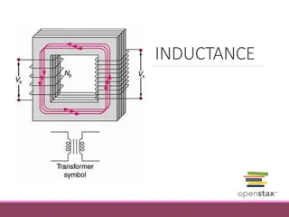
PHY1013S MAGNETISM INDUCTANCE VOLTAGE ACROSS AN INDUCTOR While the current through an inductor is steady there is no potential drop across it (R =0), but changingthe current changes the flux which inducesa current in the same coil! (Hence the term self-induction.) As current increases in the coil, the inducedcurrent tends to hold up positives at the inflow, creating an electric field and hence a potential difference across the inductor: coil E induced current induced field B + VL increasing current d dI back emf , so = = m = = coil E Ldt dt 6
PHY1013S MAGNETISM INDUCTANCE VOLTAGE ACROSS AN INDUCTOR induced current When the switch is opened, to oppose the decreasingflux in the solenoid, the induced current flows in the same direction as the decreasing current and thus establishes a forwards potential difference across the inductor. induced field + VL safety R decreasing current Since the induced emf is proportional to the rate of changeof current, a rapid decrease in even a modest amount of current can produce a very high potential difference across switch contacts, leading to sparking which may or may not be desirable. 7
PHY1013S MAGNETISM INDUCTANCE VOLTAGE ACROSS AN INDUCTOR dI = = coil E Ldt Notes We use the above in conjunction with Lenz s law. The induced emf is proportional to the rate of changeof current. It is always zero for constant I. The induced current opposes the changein the input current not the current itself. The net effect of an inductor is to make it difficult to changethe current. An inductor passes DC seamlessly, but blocks AC, and is thus sometimes referred to as a choke. 8
PHY1013S MAGNETISM INDUCTANCE ENERGY STORED IN AN INDUCTOR The rate at which current supplies energy to an inductor is: dI I V = = = = P LIdt L The rate at which this energy is stored in the inductor is: dU dt dI dt L = + = + LI i.e. the increase in energy during a time interval dt is: = = dU LIdI L Hence the total amount of energy required to increase the current through the inductor from zero to I is: I 1 2 1 2 2 2 i.e. = = L I dI = = = = U LI U U CV (Cf: ) L L C 0 9
PHY1013S MAGNETISM INDUCTANCE ENERGY DENSITY OF A MAGNETIC FIELD As a capacitor stores energy in its electric field, so an inductor actually stores energy in its magnetic field. 2 2 NI N AI 1 1 2 2 2 0 0 = = = = = = For a solenoid: A U LI 2 L 2 0 0NI where is the field inside the solenoid, B = = Hence the magnetic field energy density, uB, inside a solenoid is: 1 2 2 2 0 (Cf: ) E u = = = = E u B B 2 0 10
PHY1013S MAGNETISM INDUCTANCE RL CIRCUITS a In circuits containing both resistors and inductors, current strength varies with time. I.e. RL circuits are time dependent. At switch over from a to b, energy stored in the inductor allows it to act like a battery for a short period of time. b decreasing I + + + R L = = Applying Kirchhoff s loop law: dI RI Ldt V V 0 R L dI I dt = = = = = = dt 0 i.e. or: ( ( ) ) LR L/R= L istheinductivetimeconstantforaparticularcircuit. I t t dI I 1 = = = = and solving for I: dt I I e Hence: L 0 L 0 I 0 11
PHY1013S MAGNETISM INDUCTANCE RL CIRCUITS R t = = I I e 0 decreasing I EL At time t = 0, but as t , I0 = EL/R, , , , I + 0. = =E E 1 L L = = At time t = L, I e 0.37R R Graphically: I I0 (As before, the shape of the graph is independent of L s value.) 0.37I0 0.13I0 L 2 L 3 L 0 t 12
PHY1013S MAGNETISM INDUCTANCE RL CIRCUITS R a A long time after the switch is moved from b to a, the inductor will act like an ordinary conducting wire. + b increasing I E EL Initially, however, it acts to oppose the increasing current through it. Applying Kirchhoff s loop law: I dI = = E IR Ldt 0 E/R 0.63E/R solving which for I we get: ( ( ) ) t E = = I e 1 L R 2 3 0 t 13
PHY1013S MAGNETISM INDUCTANCE INDUCTORS vs CAPACITORS CAPACITOR INDUCTOR Has a capacity to hold charge, called capacitance [C/V= farad, F] determined by its geometry: Has an ability to hold flux, called inductance [Wb/A=T m /A= henry, H] determined by its geometry: Q V = = m I = = C L 2 A N ( 1) 2 0AN = = = = C L 0 d Circuit diagram symbol: Circuit diagram symbol: UC = C( V)2 UL = LI2 Stores energy in its electric field: Stores energy in its magnetic field: 1 2 2 = = u B 0 = = u E 2 B E 2 0 Regulates current through a series resistor ( ( ) ) t t = =E E = = I e I e 1 at switch on: at switch on: L R R t t and switch off: and switch off: = = = = I I e I I e L 0 0 14