Understanding Interrupts in PIC16F Microcontrollers
Explore the key sources of interrupts in PIC16F627A/628A/648A, accessing registers, enabling interrupts, and managing local interrupts such as Timer 0 alarms and B0 pin changes. Learn how to set interrupts on desired events and understand the corresponding flag bits for interrupt occurrence.

Download Presentation

Please find below an Image/Link to download the presentation.
The content on the website is provided AS IS for your information and personal use only. It may not be sold, licensed, or shared on other websites without obtaining consent from the author. Download presentation by click this link. If you encounter any issues during the download, it is possible that the publisher has removed the file from their server.
E N D
Presentation Transcript
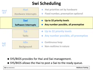
Interrupts The PIC16F627A/628A/648A has 10 sources of interrupt: External Interrupt RB0/INT * TMR0 Overflow Interrupt * PORTB Change Interrupts (pins RB<7:4>) * Comparator Interrupt USART Interrupt TX USART Interrupt RX CCP Interrupt TMR1 Overflow Interrupt * TMR2 Match Interrupt * Data EEPROM Interrupt
Interrupts IMPORTANT!!! We need to access two different registers: INTCON and OPTION. INTCON is in bank 0, OPTION is in bank 1
Interrupts to enable interrupts: bsf INTCON,GIE or bsf INTCON,7
Interrupts: lets focus on local interrupts TMR0- Timer 0 alarm has gone off B0 change on pin B0 RB PORT Change- change on one of B4,B5,B6,B7
Interrupts Suppose we wish to interrupt on : - change on B0 - when TMR0 alarms sounds bsf bsf bsf INTCON, GIE INTCON,INTE INTCON,TMIE ; enable global interrupts ; enable change of B0 interrupt ; enable Timer 0 interrupt
Interrupts Each local interrupt enable bit has a corresponding flag bit. The flag indicates that this type of interrupt has occurred: INTE INTF (B0 change ) TOIE TOIF (Timer0 alarm) RBIE RBIF (change on B4,B5,B6, or B7)
Interrupts: INTE versus RBIE INTE occurs with a change on B0. The programmer decides if the desired interrupt change is from low to high or high to low. This is specified in the OPTION register bit 6 (INTEDG) RBIE occurs with any change of state on pins B4,B5,B6,B7
Interrupts Let s set an interrupt on B0 on a rising edge: bsf INTCON,GIE bsf INTCON,INTE bsf STATUS,RP0 movlw 0x01 movwf TRISB bsf OPTION, INTEDG bcf STATUS,RP0 ; ; enable global interrupts ; enable B0 interrupt ; goto bank 1 ; portb pin 0 is input ; interrupt on low to high ;return to bank 0
Interrupts Interrupt Service Routines (ISR) always end with retfie When an interrupt occurs, the GIE is set to 0. Thus, an interrupt cannot occur while an interrupt is occurring. retfie re-enables GIE Interrupts do stack . That is, if an interrupt occurs while an interrupt is being serviced, the new interrupt will be serviced after the older interrupt finishes and retfie re-enables interrupts When an interrupt occurs, only the PC is saved on a stack. The programmer must save any other registers (like the W???) NEVER set or clear GIE in an interrupt routine
Timer 0 Timer 0 (TMR0) is an 8-bit register in bank 0 TMR0 will set the Timer 0 flag (T0IF) on overflow from 0xff to 0x00 T0IF will be set even if interrupts are not enabled (true for all interrupt flags) TMR0 will tick either from the system clock or from transitions externally (pin A4) We are interested in using Timer 0 with the system clock
Timer 0 Timer 0 users a prescaler . Think of the PIC as ticking every 1 microsecond. We can set different prescalers so that Timer 0 increments at a slower pace. Timer 0 has prescalers as follows: 2:1 increment every 2 microseconds 4:1 increment every 4 microseconds .. 256:1 increment every 256 microseconds So Timer 0 can actually give time upto 65,536 microseconds. Note, there is no 1:1 prescaler.
Timer 0: revisit OPTION register (bank 1) bcf OPTION,TOCS ; use internal clock
Timer 0 revisit OPTION register bcf bcf bcf bcf OPTION,PSA ; select Timer0, not watch dog timer OPTION,2 ; next three set prescaler to 2:1 OPTION,1 OPTION,0
Timer 0 500 microsecond timer, no interrupt Let s see: we ll need 250 clicks of the timer with a 2:1 prescaler. So we will load TMR0 with the value 0x06. bsf ; select system clock (bit 5), TMR0(bit 3), prescaler 2:1( bits 2-0) movlw 0x00 movwf OPTION bcf STATUS,RP0 movlw0x06 movwf TMR0 btfss INTCON,T0IF goto $-1 STATUS,RP0 ; goto bank 1 ; set bits 5,3,0-2 ;return to bank 0 ; place a 6 in timer ; overflow?
Timer 0 generate an interrupt in 500 microseconds (set up is in main) bsf bsf bsf movlw movwf bcf movlw movwf Blah blah blah INTCON,GIE INTCON,T0IE STATUS,RP0 0x00 OPTION STATUS,RP0 ; 0x06 TMR0 ; go on your merry way, interrupt in 500 micros ; enable global interrupts ; enable Timer 0 interrupt ; goto bank 1 ; system clock, timer 0, 2:1 prescaler ; portb pin 0 is input ;return to bank 0
Coding it main must reside at 0x00 and ISR must reside at 0x04. Typical layout: org goto org goto 0x00 main 0x04 isr isr ... ...... retfie main ...... ...... end
Coding it An interrupt clears GIE, retfie resets it. Leave it alone!! An interrupt sets the specific interrupt flag. You must clear it before you execute retfie. Otherwise, the interrupt will never occur again. If you have enabled several interrupts, your interrupt routine must poll the interrupt flags to determine which interrupts occurred. You may service multiple interrupts in a routine. If you don t, the subsequent interrupts will be triggered immediately upon executing a retfie.


")