IEEE 802.11-19/0773r0 Multi-link Operation Framework Summary
The document discusses the multi-link operation framework for IEEE 802.11-19/0773r0, focusing on load balancing and aggregation use cases. It introduces terminology related to multi-link logical entities and provides examples of multi-link AP and non-AP logical entities. The framework considers steering/load balancing scenarios and aggregation use cases within the context of multi-link AP and non-AP logical entities.
Download Presentation

Please find below an Image/Link to download the presentation.
The content on the website is provided AS IS for your information and personal use only. It may not be sold, licensed, or shared on other websites without obtaining consent from the author. Download presentation by click this link. If you encounter any issues during the download, it is possible that the publisher has removed the file from their server.
E N D
Presentation Transcript
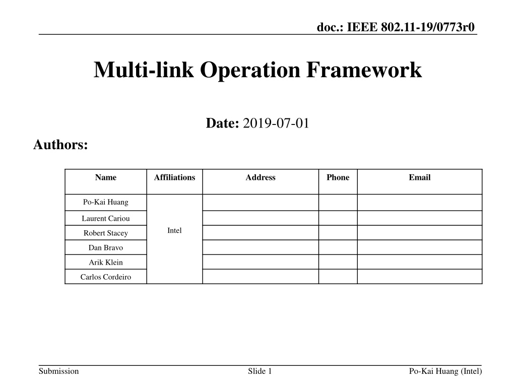
doc.: IEEE 802.11-19/0773r0 Multi-link Operation Framework Date: 2019-07-01 Authors: Name Affiliations Address Phone Email Po-Kai Huang Laurent Cariou Intel Robert Stacey Dan Bravo Arik Klein Carlos Cordeiro Submission Slide 1 Po-Kai Huang (Intel)
doc.: IEEE 802.11-19/0773r0 Abstract Multi-link operation has been discussed in [2-6] for the use cases of load balancing [2,4] and aggregation [3-6] The presentation provides the follow up for multi-link operation Submission Slide 2 Po-Kai Huang (Intel)
doc.: IEEE 802.11-19/0773r0 Terminology Recap [2,4] Extremely efficient multi-link operation calls for a new definition of multi-link logical entity with one or more affiliated STAs The logical entity has one MAC data service interface and primitives to the LLC and a single address associated with the interface, which can be used to communicate on the DSM. Multi-link AP logical entity: A multi-link logical entity, where each affiliated STA is an AP. Multi-link non-AP logical entity: A multi-link logical entity, where each STA is a non-AP STA. This definition keeps within the current 802.11 architecture and definition of STA and link Submission Po-Kai Huang (Intel) Slide 3
doc.: IEEE 802.11-19/0773r0 Terminology Recap [2] Example 1 Example 2 Multi-link AP logical entity Multi-link AP logical entity AP2 operating on 5 GHz configuration 1 AP3 operating on 5 GHz configuration 2 AP1 operating on 2.4 GHz AP2 operating on 5 GHz AP3 operating on 6 GHz AP1 operating on 2.4 GHz DS DSM Link 1 Link 2 Link 3 Link 1 Link 2 Link 3 Non-AP STA1 Non-AP STA2 Non-AP STA3 Non-AP STA1 Non-AP STA2 Non-AP STA3 Multi-link non-AP logical entity Multi-link non-AP logical entity Multi-link AP logical entity/Multi-link non-AP logical entity has an address to communicate to DSM, which may not be the address used on each WM Submission
doc.: IEEE 802.11-19/0773r0 Steering/load balancing Use Case under the Framework [2] Multi-link AP logical entity Multi-link AP logical entity DS AP1 operating on 2.4 GHz AP2 operating on 5 GHz AP3 operating on 6 GHz AP1 operating on 2.4 GHz AP2 operating on 5 GHz AP3 operating on 6 GHz DSM TBD Mechanism Link 1 Link 2 Link 3 Link 1 Link 2 Link 3 Non-AP STA1 Non-AP STA2 Non-AP STA3 Non-AP STA1 Non-AP STA2 Non-AP STA3 Multi-link non-AP logical entity Multi-link non-AP logical entity Submission
doc.: IEEE 802.11-19/0773r0 Aggregation Use case under the Framework [2] Multi-link AP logical entity Multi-link AP logical entity AP1 operating on 2.4 GHz AP2 operating on 5 GHz AP3 operating on 6 GHz AP1 operating on 2.4 GHz AP2 operating on 5 GHz AP3 operating on 6 GHz DS DSM TBD Mechanism Link 1 Link 2 Link 3 Link 1 Link 2 Link 3 Non-AP STA1 Non-AP STA2 Non-AP STA3 Non-AP STA1 Non-AP STA2 Non-AP STA3 Multi-link non-AP logical entity Multi-link non-AP logical entity Submission
doc.: IEEE 802.11-19/0773r0 Multi-link Setup Traditionally, single link setup is achieved through the functionality of association. Executed over one link initiated by a non-AP STA with an AP Capability for one birdirectional link can be exchanged during the association The AP serves as the interface to the distribution system (DS) for the non-AP STA after successful association For Multi-link setup, an association like multi-link setup signaling exchange is needed Executed over one link initiated by a multi-link non-AP logical entity with a multi- link AP logical entity Capability for one or more bidirectional links can be exchanged during the multi- link setup The multi-link AP logical entity serves as the interface to the distribution system (DS) for the multi-link non-AP logical entity after successful multi-link setup Submission Slide 7 Po-Kai Huang (Intel)
doc.: IEEE 802.11-19/0773r0 Illustration of Single Link Association AP1 operating on 2.4 GHz AP1 operating on 2.4 GHz DS Association Response frame for with capability of AP1, configuration of link 1 Association Request frame with capability of non-AP STA1 DSM Link 1 Non-AP STA1 Non-AP STA1 Submission Slide 8 Po-Kai Huang (Intel)
doc.: IEEE 802.11-19/0773r0 Illustration of Multi-link Setup AP1 operating on 2.4 GHz Multi-link AP logical entity DS AP1 operating on 2.4 GHz AP2 operating on 5 GHz AP3 operating on 6 GHz DSM Response frame for multi-link setup with capability of AP1/2/3, configuration of link 1/2/3 Request frame for multi-link setup with capability of non-AP STA1/2/3 Link 1 Link 2 Link 3 Non-AP STA1 Non-AP STA2 Non-AP STA3 Multi-link non-AP logical entity Non-AP STA1 Submission Slide 9 Po-Kai Huang (Intel)
doc.: IEEE 802.11-19/0773r0 Enable Link After single link association, the link used for association singling exchange is enabled for class 2 and class 3 frame exchange (see Figure 11-16 [7]) For multi-link setup, due to the nature of multiple links, different simultaneous operation capability, power save consideration, there is a need to Define a mechanism to determine, during or after successful completion of multi-link setup, which bidirectional link(s) is(are) enabled for class 2 and class 3 frame exchange after multi-link setup A identification for each link may be needed, but details are TBD Submission Slide 10 Po-Kai Huang (Intel)
doc.: IEEE 802.11-19/0773r0 Multi-link Capability Simultaneous operation across links provides gains but also corresponding hardware investment We envision that the benefits multi-link operation can be enjoyed by a range of devices that support various capability of simultaneous operation across links To achieve this goal, A multi-link logical entity can indicate capability to support exchanging frames simultaneously on a set of affiliated STAs Submission Slide 11 Po-Kai Huang (Intel)
doc.: IEEE 802.11-19/0773r0 Conclusion We provide multi-link operation follow up to propose a unified framework that addresses the key use cases (load balancing and aggergation) and keeps within the current 802.11 architecture and definition Multi-link logical entity, Multi-link AP logical entity, and Multi- link non-AP logical entity are defined We propose to define multi-link setup, which is analogous to single-link association We propose to define multi-link capability indication, which enables multi-link operation for a wide range of devices Submission Slide 12 Po-Kai Huang (Intel)
doc.: IEEE 802.11-19/0773r0 Straw Poll #1 - Terminology Do you support the following definition: Multi-link logical entity: A logical entity that has one or more affiliated STAs. The logical entity has one MAC data service interface and primitives to the LLC and a single address associated with the interface, which can be used to communicate on the DSM. Multi-link AP logical entity: A multi-link logical entity, where each STA within the multi-link logical entity is an AP. Multi-link non-AP logical entity: A multi-link logical entity, where each STA within the multi-link logical entity is a non-AP STA. NOTE A Multi-link logical entity allows STAs within the multi- link logical entity to have the same MAC address NOTE The exact name can be changed Submission Slide 13 Po-Kai Huang (Intel)
doc.: IEEE 802.11-19/0773r0 Straw Poll #2 Multi-link Setup Do you support the following: Define a multi-link setup signaling exchange executed over one link initiated by a multi-link non-AP logical entity with a multi-link AP logical entity as follows: Capability for one or more bidirectional links can be exchanged during the multi-link setup The multi-link AP logical entity serves as the interface to the distribution system (DS) for the multi-link non-AP logical entity after successful multi-link setup Define a mechanism to determine, during or after successful completion of multi-link setup, which bidirectional link(s) is(are) enabled for class 2 and class 3 frame exchange after multi-link setup NOTE - The link identification is TBD NOTE Details for non-infrastructure mode of operation TBD Submission Slide 14 Po-Kai Huang (Intel)
doc.: IEEE 802.11-19/0773r0 Straw Poll #3 Multi-link Capability Do you support that a multi-link logical entity can indicate capability to support exchanging frames simultaneously on a set of affiliated STAs? Submission Slide 15 Po-Kai Huang (Intel)
doc.: IEEE 802.11-19/0773r0 Reference [1] 11-18/1231r4 EHT draft proposed PAR [2] 11-19/0822r0 Extremely Efficient Multi-band Operation [3] 11-19/0731r0 Multi-link Operation [4] 11-19/0823r0 Multi-Link Aggregation [5] 11-19/0766r1 Enhanced Multi-band/Multi-channel Operation [6] 11-19/0821r0 Multiple Band Operation Discussion [7] Draft P802.11REVmd D2.2 Submission Slide 16 Po-Kai Huang (Intel)
