Understanding Logic Problems and Truth Tables
Explore the process of solving logic problems using truth tables, from defining the problem to implementing solutions in hardware and software. Learn to identify inputs and outputs, select appropriate truth tables, fill in truth tables, document solutions, and simplify solutions using Boolean Algebra or Karnaugh Maps.
Download Presentation

Please find below an Image/Link to download the presentation.
The content on the website is provided AS IS for your information and personal use only. It may not be sold, licensed, or shared on other websites without obtaining consent from the author. Download presentation by click this link. If you encounter any issues during the download, it is possible that the publisher has removed the file from their server.
E N D
Presentation Transcript
Solving Logic Problems using Truth Tables
Solving Logic Problems using Truth Tables Defining a Logic Problem Selecting and Using an appropriate Truth Table Using Truth Tables to determine the solution to a Logic Problem Implementing the solution using hardware (engineering) Implementing the solution using software (computer science)
Defining a Logic Problem The assumption for this lesson is that a logic problem consists of Binary inputs all inputs are yes/no, on/off, or true/false inputs Binary outputs the output(s) are yes/no, on/off, or true/false The state of the output is based on the state of the inputs Example: If the burglar alarm is engaged and a window is open or motion is detected, sound the alarm.
Identify the Inputs and Outputs For each input and output, identify what constitutes on and off (true and false). Example: If the burglar alarm is turn on and a window is open or motion is detected, sound an audible alarm. Inputs Burglar Alarm: 1 Alarm On, 0 Alarm Off Window: 1 Closed, 0 Open Motion Detector: 1 Motion, 0 No Motion Outputs Alarm: 1 On, 0 Off
Select an appropriate Truth Table The appropriate Truth Table is based on the number of inputs Two Inputs Three Inputs Four Inputs
Fill in the Truth Table X 0 0 0 0 1 1 1 1 Y 0 0 1 1 0 0 1 1 Z 0 1 0 1 0 1 0 1 Out 0 0 0 0 1 1 0 1 X = Burglar Alarm: 1 Alarm On, 0 Alarm Off Y = Window: 1 Closed, 0 Open Z = Motion Detector: 1 Motion, 0 No Motion Out = Alarm: 1 On, 0 - Off
Document the Solution Identify the inputs that cause the output to be 1. These are the min-terms. Write the equation for each min-term. If an input is 1, write the variable name. If the input is 0, write the inverse of the variable name. If X = 0, use ? If X = 1, use ? Inputs are AND ed (the first min-term is ? ? ?) Combine min-terms to form the equation Min-terms are OR ed The full solution is ? ? ? + ? ?? + ???
Simplify the Solution Solutions can be simplified using Boolean Algebra or Karnaugh Mapping. These topics are beyond the scope this lesson, therefore this lesson will use unsimplified logic expressions.
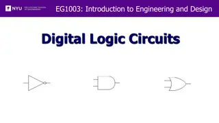
Test the Solution (Hardware) ? ? ? + ? ?? + ??? 1) Invert any inputs that have to be inverted using an Inverter Gate
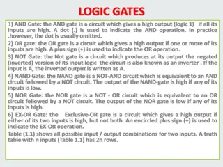
Test the Solution (Hardware) ? ? ? + ? ?? + ??? 2) AND the inputs to form a min-term using an AND Gate
Test the Solution (Hardware) ? ? ? + ? ?? + ??? 3) OR the min-terms to form the solution using an OR Gate
Test the Solution (Software) ? ? ? + ? ?? + ??? o) Define variables for each input. A common practice is name the variable after the positive (true) state
Test the Solution (Software) ? ? ? + ? ?? + ??? 1) Invert any inputs that have to be inverted using the inversion operator
Test the Solution (Hardware) ? ? ? + ? ?? + ??? 2) AND the inputs to form a min-term using AND operators
Test the Solution (Software) ? ? ? + ? ?? + ??? 3) OR the min-terms to form the solution using an OR Gate
References Digital Logic Circuits created in National Instruments Multisim Block-Based Code created in littleBits Code Kit Text-Based Code created in Notepad++
