Understanding Image Morphing Techniques
Explore the fascinating world of image morphing, computational photography, and gradient domain editing through transformation concepts, take-home questions, and practical applications such as texturing in transformed coordinates and forward mapping. Delve into the issues and solutions related to forward and inverse mappings in image processing.

Download Presentation

Please find below an Image/Link to download the presentation.
The content on the website is provided AS IS for your information and personal use only. It may not be sold, licensed, or shared on other websites without obtaining consent from the author. Download presentation by click this link. If you encounter any issues during the download, it is possible that the publisher has removed the file from their server.
E N D
Presentation Transcript
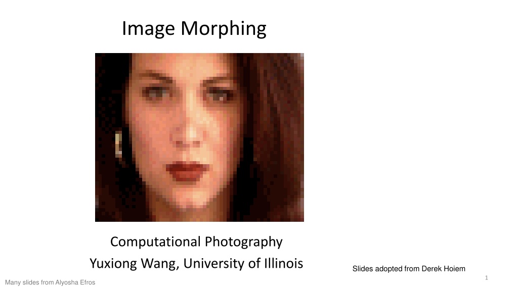
Image Morphing Computational Photography Yuxiong Wang, University of Illinois Slides adopted from Derek Hoiem 1 Many slides from Alyosha Efros
Project 3: Gradient Domain Editing General concept: Solve for pixels of new image that satisfy constraints on the gradient and the intensity Constraints can be from one image (for filtering) or more (for blending) 2
2D image transformations These transformations are a nested set of groups Closed under composition and inverse is a member 3
Take-home Question Suppose we have two triangles: ABC and A B C . What transformation will map A to A , B to B , and C to C ? How can we get the parameters? B B ? T(x,y) C A C A Source Destination 4
Today: Morphing Women in art http://youtube.com/watch?v=nUDIoN-_Hxs Aging 5 http://www.youtube.com/watch?v=L0GKp-uvjO0
Texturing in transformed coordinates T(x,y) y y x x f(x,y) g(x ,y ) Given a coordinate transform (x ,y )=T(x,y) and a source image f(x,y), how do we compute a transformed image g(x ,y )=f(T(x,y))? 6
Forward mapping T(x,y) y y x x f(x,y) g(x ,y ) Send each pixel f(x,y) to its corresponding location (x ,y )=T(x,y) in the second image 7
Forward mapping What is the problem with this approach? T(x,y) y y x x f(x,y) g(x ,y ) Send each pixel f(x,y) to its corresponding location (x ,y )=T(x,y) in the second image Q: what if pixel lands between two pixels? A: distribute color among neighboring pixels (x ,y ) Known as splatting 8
Inverse mapping T-1(x,y) y y x x x f(x,y) g(x ,y ) Get each pixel g(x ,y ) from its corresponding location (x,y)=T-1(x ,y ) in the first image Q: what if pixel comes from between two pixels? 9
Inverse mapping T-1(x,y) y y x x x f(x,y) g(x ,y ) Get each pixel g(x ,y ) from its corresponding location (x,y)=T-1(x ,y ) in the first image Q: what if pixel comes from between two pixels? A: Interpolate color value from neighbors nearest neighbor, bilinear, Gaussian, bicubic E.g. interpolate.interp2 or ndimage.map_coordinates in Python scipy 10
Bilinear Interpolation 11 http://en.wikipedia.org/wiki/Bilinear_interpolation
Forward vs. inverse mapping Q: which is better? A: Usually inverse eliminates holes however, it requires an invertible warp function 12
Morphing = Object Averaging The aim is to find an average between two objects Not an average of two images of objects but an image of the average object! How can we make a smooth transition in time? Do a weighted average over time t 13
Averaging Points Q v = Q - P What s the average of P and Q? P Extrapolation: t<0 or t>1 P + 1.5v = P + 1.5(Q P) = -0.5P + 1.5 Q (t=1.5) Linear Interpolation New point: P + t*(Q-P) Or equivalently: (1-t)P + tQ 0<t<1 P + 0.5v = P + 0.5(Q P) = 0.5P + 0.5 Q P and Q can be anything: points on a plane (2D) or in space (3D) Colors in RGB (3D) Whole images (m-by-n D) etc. 14
Idea #1: Cross-Dissolve Interpolate whole images: Imagehalfway = (1-t)*Image1 + t*image2 This is called cross-dissolve in film industry But what if the images are not aligned? 15
Idea #2: Align, then cross-disolve Align first, then cross-dissolve Alignment using global warp picture still valid 16 Image credit: Efros
Dog Averaging What to do? Cross-dissolve doesn t work Global alignment doesn t work Cannot be done with a global transformation (e.g. affine) Any ideas? Feature matching! Nose to nose, tail to tail, etc. This is a local (non-parametric) warp 17
Idea #3: Local warp, then cross-dissolve Morphing procedure For every frame t, 1. Find the average shape (the mean dog ) local warping 2. Find the average color Cross-dissolve the warped images 18
Local (non-parametric) Image Warping Need to specify a more detailed warp function Global warps were functions of a few (2,4,8) parameters Non-parametric warps u(x,y) and v(x,y) can be defined independently for every single location x,y! Once we know vector field u,v we can easily warp each pixel (use backward warping with interpolation) 19
Image Warping non-parametric Move control points to specify a spline warp Spline produces a smooth vector field 20
Warp specification - dense How can we specify the warp? Specify corresponding spline control points interpolate to a complete warping function But we want to specify only a few points, not a grid 21
Warp specification - sparse How can we specify the warp? Specify corresponding points interpolate to a complete warping function How do we do it? How do we go from feature points to pixels? 22
Triangular Mesh 1. Input correspondences at key feature points 2. Define a triangular mesh over the points Same mesh (triangulation) in both images! Now we have triangle-to-triangle correspondences 3. Warp each triangle separately from source to destination Affine warp with three corresponding points (just like take- home question) 23
Triangulations A triangulation of set of points in the plane is a partition of the convex hull to triangles whose vertices are the points, and do not contain other points. There are an exponential number of triangulations of a point set. 24
An O(n3) Triangulation Algorithm Repeat until impossible: Select two sites. If the edge connecting them does not intersect previous edges, keep it. 25
Quality Triangulations Let (Ti) = ( i1, i2 , i3 ,...) be the vector of angles in the triangulation T in increasing order: A triangulation T1 is better than T2 if the smallest angle of T1 is larger than the smallest angle of T2 Delaunay triangulation is the best (maximizes the smallest angles) good bad 26
Improving a Triangulation In any convex quadrangle, an edge flip is possible. If this flip improves the triangulation locally, it also improves the global triangulation. If an edge flip improves the triangulation, the first edge is called illegal . 27
Nave Delaunay Algorithm Start with an arbitrary triangulation. Flip any illegal edge until no more exist. Could take a long time to terminate. 29
Delaunay Triangulation by Duality Draw the dual to the Voronoi diagram by connecting each two neighboring sites in the Voronoi diagram. The DT may be constructed in O(nlogn) time Demos: http://www.cs.cornell.edu/home/chew/Delaunay.html http://alexbeutel.com/webgl/voronoi.html 30
Image Morphing How do we create a morphing sequence? 1. Create an intermediate shape (by interpolation) 2. Warp both images towards it 3. Cross-dissolve the colors in the newly warped images 31
Warp interpolation How do we create an intermediate shape at time t? Assume t = [0,1] Simple linear interpolation of each feature pair (1-t)*p1+t*p0 for corresponding features p0 and p1 32
Morphing & matting Extract foreground first to avoid artifacts in the background 33 Slide by Durand and Freeman
Dynamic Scene Black or White (MJ): http://www.youtube.com/watch?v=R4kLKv5gtxc Willow morph: http://www.youtube.com/watch?v=uLUyuWo3pG0 34
Summary of morphing 1. Define corresponding points 2. Define triangulation on points Use same triangulation for both images 3. For each t = 0:step:1 a. Compute the average shape (weighted average of points) b. For each triangle in the average shape Get the affine projection to the corresponding triangles in each image For each pixel in the triangle, find the corresponding points in each image and set value to weighted average (optionally use interpolation) c. Save the image as the next frame of the sequence 35
Next classes Pinhole camera: start of perspective geometry Single-view metrology: measure 3D distances from an image 36


 Image Warping")


 Triangulation Algorithm")