Understanding Microcontroller Interrupts and Applications

Explore the fundamental concepts of interrupts, PWM, timer/counters, and ADC in microcontrollers. Learn how to use interrupts for tasks like LED blinking, control LED brightness with PWM, and read voltage using ADC. Get insights on interrupt routines, enabling interrupts through registers, and tips for effective interrupt handling.

Download Presentation

Please find below an Image/Link to download the presentation.
The content on the website is provided AS IS for your information and personal use only. It may not be sold, licensed, or shared on other websites without obtaining consent from the author. Download presentation by click this link. If you encounter any issues during the download, it is possible that the publisher has removed the file from their server.
E N D
Presentation Transcript
Agenda We will learn 4 new concepts: - Interrupts - PWM (Phase-Width-Modulation) - Timer/counter - ADC (Analog-Digital-Converter) Tasks: - Use interrupts to get LEDs to blink at even intervals - Use PWM to control the brightness of LEDs - Read voltage from a potmeter using ADC
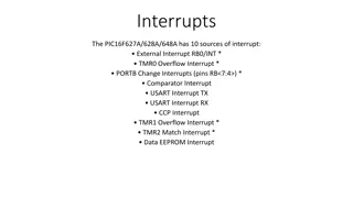
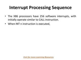
Interrupts - Code blocks that are executed immediately when a precondition is met ( interrupts normal execution) - Stops the main program flow temporarily, resumes immediately after interrupt Main program Main program resumed Interrupt code Time
Interrupts - Useful if you have a piece of code that only needs to execute once in a while - Button handling, receive message etc - Frees up the CPU to do other things Main program Main program resumed Interrupt code Time
Interrupt routine Special function thats called automatically when both: - interrupt request preconditions met - the corresponding interrupt is enabled - global interrupts are enabled
Interrupts - Interrupts must be enabled through registers:
Interrupt routine - To declare: - ISR = Interrupt Service Routine (macro) - TCA0_OVF_vect = the interrupt vector name - Requires #include <avr/interrupt.h> Remember to call sei() to enable global interrupts -
Interrupt routine - Interrupt vectors are found in the data sheet. - Other possible vectors for the timer A module:
Interrupt routine In <avr/interrupt.h> they are defined as follows:
Interrupts a few tips - MegaAVR 0-Series has two interrupts levels, 0 (default) and 1. - Keep your interrupts short (in terms of execution time) - Interrupts are often, but not always, the answer to your problems
Event System - Peripheral to peripheral communication - Enables reaction to precondition without involving the CPU - Great for low power and time critical tasks - Six channels
PWM - - From wikipedia: In electronics and telecommunications, modulation is the process of varying one or more properties of a periodic waveform, called the carrier signal, with a modulating signal that typically contains information to be transmitted.
PWM Useful for plenty of things: - Motor control - Led brightness control - Information transmission over long wires - Digital to analog converters - Etc When used with a LED it will make the it appear more or less bright, proportional to the Duty Cycle. The higher the Duty cycle, the more light from the LED.
USART Universal Synchronous Asynchronous Receiver Transmitter Simple communications protocol Synchronous = extra wire for shared clock Asynchronous = no wire for shared clock Data usually sent in chunks of 8 bits Can have simple error checking
UART We use asynchronous mode in this assignment Asynchronous means that both parts need to know what speed is being used Baudrate = symbol rate, transmission speed, must be correctly set. In this lab, we use a baud rate of 9600. Note: This is NOT the value to be inserted in the BAUD register.
UART - BAUD register value: The value to insert into the baud register is calculated based on the desired baud rate and the frequency of the peripheral clock. S = 16 (normal mode ) f_baud = 9600 CLK_PER = 3.33 MHz
UART Extra components on the dev board do uart<->USB translation - Enables sending data to your computer using UART - Receive/transmit with PUTTY or similar programs
UART Necessary setup of UART: - Set data length - Set baudrate (transmission speed) - Set number of stop bits - Select asynchronous operation - Enable receiver and transmitter
Timer/Counter Dedicated unit for counting clock cycles Extremely versatile units Can for example be used to generate a PWM signal:
Timer/Counter MegaAVR 0-Series has three timer types: A: specialized for waveform generation (16 bit) B: specialized for input capture and timing checks (16 bit) D: specialized for motor control etc We focus on the type A
Timer/Counter Can run in different modes:
Timer/Counter Prescaling: A prescaler divides the input frequency by a fixed integer value. The input to the timer is 3.33MHz by default. By using the timer prescaler, you can make it run slower (count for longer)
PWM with Timer Dedicated pins on the 4809 is connected to the timers. (0-WO0 to 0-WO5). 0-WO1 is connected to port A, pin 1. If the corresponding compare match is enabled and correct mode is selected, a PWM waveform will be generated on the pin.
PWM with Timer Set the period by modifying the TOP value and the counter speed (prescaler value). Example: If input clock of a 16-bit counter is 3.33MHz, what must prescaler and TOP value be for a period of ~ 20ms? Many solutions, examples: Prescaler = 16 Prescaler = 8, Prescaler = 4, TOP = 4 166 TOP = 8 333 TOP = 16 666
PWM with Timer Set the Duty Cycle by modifying the compare value. Example: For the settings in the previous slide, what value must compare be for a Duty Cycle of 50%? Duty Cycle = Compare value / top value For a duty cycle of 50%, Compare value = top value * 0.5 For a duty cycle of 25%, Compare value = top value * 0.25 Etc
Timer/Counter Typical setup: - Set WO pins as output - Enable timer - Select timer mode - Select prescaling factor - Select top value (if aplicable) - Select compare value (if applicable) (comp registers) - Enable compare match - Implement ISR (if applicable) - Enable interrupt (if applicable) - Enable global interrupts (portx.dir-register) (ctrl-registers) (ctrl-registers) (ctrl-registers) (per registers) (ctrl-registers) (intctrl-registers) ( sei() )
Timer/Counter Note about inverted LEDs: Since the LEDs on the board are active LOW, you need to invert the phase of the PWM in one of two possible ways: 1) Invert the output pins directly in the PORT module 2) Invert the value in the compare register like so: InvertedCompareVal = TOP regularCompareVal In other words, for option 2: CompareVal = TOP CompareVal = 0 => LEDs off => LEDs max on
Analog-to-digital converter (ADC) Converts an analog, continuous, signal into discrete representation. Both continuous time and voltage are converted into discrete values in a conversion. Resolution measured in bits (eq. 10 bits) Sampling rate (or sampling frequency) determines the rate at which values are converted. Nyquist theorem states that the sample frequency has to be twice that of the highest frequency in the sampled signal (Fs >= 2* Fsig)
ADC usage on the AVR Initializing an ADC on the AVR can be accomplished like this: Set the bit resolution (we use 8 bit in this task) Select the reference voltage Set the ADC clock prescaler so the speed is between 50kHz and 2MHz Enable the ADC Getting a sample from the ADC: Choose which ADC input channel to use Clear the ADC conversion done interrupt flag. Start a new conversion. Wait for the conversion to complete by monitoring the interrupt flag. Read out the value from the result register.
Agenda Tasks: Timers - Set up a timer to blink a LED by generating interrupts - Set up a timer to dim a LED by automatic compare matching ADC - Set up the ADC to read voltage from a potmeter. The result can be transmitted over UART


")