Understanding Heightmap Segmentation in DICOM Imaging
 undefined
Heightmap Segmentation
To accompany Sup240 Public Comment

Topics
•
Heightmap
•
Classic segmentation in DICOM
(background information)
•
Heightmap segmentation
•
1D and 2D
•
Notes and clarifications
•
Heightmap use in derived En Face Images
Heightmap definition
(computer graphics) A two-dimensional raster
image used to store surface elevations that
can later be applied to a three-dimensional
object.
https://en.wiktionary.org/wiki/heightmap
Heightmap in DICOM
Use case: identify surface in a 3D volume
•
Restricted to single height (z) at any baseline location (x,y)
•
Initial primary use for retinal layer surfaces in ophthalmic
tomography (OPT)
•
Degenerate case - intersection of surface with single image
plane (1D raster for 2D object)
Mechanism: Heightmap Segmentation IOD
•
Modeled on Segmentation IOD
Simplified alternative to Surface Segmentation IOD,
which allows arbitrary (folded, volume) surfaces
Segmentation (general background)
Important analytic task is identifying the different anatomical
features in an image
•
Bones, organs, tumors, blood
•
Brain areas that are active with stimulus (functional MRI)
Segmentation classifies areas, volumes, or surfaces in
categories
Segments can feed into imaging display pipelines
•
As overlay or blending with source image (e.g., with Blending
Softcopy Presentation State)
•
Virtual removal of background or segmented anatomy from
display of source (e.g., with Volumetric Presentation State)
Segments can feed into quantitative measurements
DICOM “classic”
(pixel/voxel
)
segmentation
Modality = “SEG”
Derived image object using
enhanced multi-frame image paradigm
Multiple segments per object, each having a property
(categorization)
Segments linked to one or more frames, pixels show
presence of property at pixel location
Two disparate methods in single SOP Class – planar and
volumetric
Planar (pixel) segmentation
For segmentation of projection or other single plane
images
•
Possibly including each slice in a CT or MR volume (multi-
frame, or series of single frames)
Indicated by absence of Frame of Reference UID
Each segmentation frame references its
corresponding source single frame
•
AKA “derivation image”
Segmentation frame pixels are 1:1 with source
•
Same pixel matrix size, spacing
Volumetric (voxel) segmentation
Segmentation object uses same Frame of Reference as
source image(s)
Extent of SEG frames may differ from extent of source, may
use different spatial resolution, different orientation
•
Frame location in Frame of Reference specified by Pixel Measures,
Plane Position (Patient), and Plane Orientation (Patient) functional
groups
Segmented volume identified by Frame of Reference UID may
correspond to multiple single frame objects in a source series
•
E.g., for classical CT or MR SOP Instances
•
Single Segmentation object may reference such multiple source images
Note: similar approach
NOT
used in Heightmap Segmentation
Segmentation data structure
S
e
g
m
e
n
t
S
e
q
u
e
n
c
e
:
Catalog of
properties
F
u
n
c
t
i
o
n
a
l
G
r
o
u
p
S
e
q
u
e
n
c
e
:
A
t
t
r
i
b
u
t
e
s
a
n
d
c
l
a
s
s
i
f
i
c
a
t
i
o
n
o
f
e
a
c
h
f
r
a
m
e
P
i
x
e
l
D
a
t
a
:
Stream of
multiple frames
Segment Sequence (0062,0002)
Catalog of segmentation properties
•
Identifier, label, description
•
Algorithm used
•
Property category (e.g., anatomy, physical object,
functional locus) - CID 7150
•
Specific property (e.g., liver, pacemaker, perfusion)
– CID 7151
•
Preferred display color
Heightmap
segmentation
Locates a surface intersecting an
image plane or volume by its height (distance) from a
baseline
Reuses
planar
segmentation data mechanism
•
Enhanced multi-frame image paradigm
•
Multiple segments per object, each having a property
•
Each segmentation frame references its corresponding
source
•
Pixel spacing is 1:1 with source
Derivation (Source) Image
Heightmap is specified in the volumetric space
(Frame of Reference) of referenced Derivation
Image(s)
Identified in Derivation Image Functional Group
•
Derivation Code Sequence (113076, DCM,
"Segmentation"); Purpose of Reference (121322, DCM,
"Source Image for Image Processing Operation")
•
For consistency with Segmentation IOD planar
segmentation codes
2D and 1D Heightmaps
Heightmap for a 3D volume is a 2D plane
Heightmap for a 2D plane is a 1D raster (row)
Heightmap Segmentation IOD supports 1D or
2D frames
Heightmap follows DICOM convention of
measuring pixel offsets from top of frame
(TLHC)
Heightmap segmentation
1D
frame
Each Heightmap 1D frame is
one row
with number of columns
the same as corresponding source (Derivation Image) frame
Heightmap stored pixel values represent distance from top in
source image in units of pixel rows (sub-pixel resolution)
•
Upper edge of top pixel is 0.0, center of top pixel is 0.5
Heightmap 1D frames for various OPT
scan patterns
Multi-frame Ophthalmic Tomography (OPT) image may have
b-scans at varying plane orientations
•
E.g., radial scan pattern, circular scan pattern
One Heightmap 1D frame for each segmented layer in each
source b-scan frame
OPT radial scan frame orientations
relative to OP retinal image
Heightmap
2D
frames for volumetric OPT
scan patterns
OPT image may have b-scans at constant plane orientation
and regular plane spacing
•
E.g., cube scan pattern
One Heightmap 2D frame for each segmented layer covers all
source B-scan frames
•
Pixel Data same as stream of 1D Heightmap rows for each
source frame
•
Column spacing same as source column
spacing, row spacing same as
source frame spacing
heightmap 2D frame values rendered as offsets into
a 3D volume
Heightmap 2D frame pixel values rendered as
offsets into a Derivation Image 3D volume
Derivation
Image frames
Derivation Image
columns
Derivation
Image
rows
Heightmap
rows
Heightmap
columns
Heightmap pixel matrix spacing based on
Derivation Image spacing
2D Heightmap Frame Row Spacing
Equal to slice spacing in referenced derivation image
•
Spacing Between Slices (0018,0088) might not be
present in OPT images
•
S
l
i
c
e
T
h
i
c
k
n
e
s
s
(
0
0
1
8
,
0
0
5
0
)
i
s
t
e
c
h
n
i
c
a
l
l
y
a
n
i
n
c
o
r
r
e
c
t
s
u
b
s
t
i
t
u
t
e
–
e
v
e
n
t
h
o
u
g
h
i
t
i
s
c
o
m
m
o
n
l
y
u
s
e
d
a
s
i
t
i
s
a
r
e
q
u
i
r
e
d
a
t
t
r
i
b
u
t
e
Correctly should be computed from differences in
Image Position (Patient) (0020,0032) in referenced
Derivation Image
Heightmap position and orientation based
on Derivation Image
Referenced images
Heightmap is specified in the volumetric space
(Frame of Reference) of a referenced Derivation
Image
•
Identified in Derivation Image Functional Group
•
Frame of Reference Coordinate System may be deformed –
see CP2347 “Clarify OPT Frame of Reference Coordinate
System”
Heightmap may be computed from a different object
(e.g., Raw Data) identified in Referenced Image
Functional Group
OPT Acquisition and Display
Frame of Reference Coordinate System
Heightmap follows OPT frame location in space and
coordinate system, including for circular or other non-linear
scans
Typical 6x6mm scan area
Deformation is small, and
measurements in image are
corrected by (proprietary)
algorithms
CP2347 clarifies that it is
nominally
in the Patient-
based Coordinate System,
with caveat for possible
deformation
N::M Relationship between OPT and
SEG Instances
Heightmap SOP Instance can record multiple layers
(segments)
One Heightmap SOP Instance can be applied to multiple OPT
SOP Instances (e.g., if OPTs are one frame per instance)
•
All OPTs (and Heightmap) must have same Frame of
Reference UID
Multiple Heightmap SOP Instances can be applied to single
OPT SOP Instances (e.g., one layer per Heightmap instance)
Pixel Values
Heightmap pixel data values use 32-bit floating point
VR for sub-pixel resolution of position in anatomic
image
Absence of segment in a column indicated by value
in range specified by Float Pixel Padding Value
(0028,0122) and Float Pixel Padding Range Limit
(0028,0124)
CP2352 in process to clarify whether IEEE 754 NaN
(Not a Number) values are legal (e.g., for padding)
Use in non-OPT contexts
Initial use case for segmenting retinal layers in OPT
No ophthalmic-specific vocabulary or constructs
Major constraint is geometric assumptions
•
Derivation image frames perpendicular to heightmap
baseline plane
•
Rows of heightmap data correspond to the top rows of
Derivation Image frames
•
Columns of the Heightmap Segmentation correspond to the
frames of the Derivation Image
Heightmap in En Face Image
Ophthalmic OCT En Face Image presents a cross-sectional
slab of OPT or OPT Volume Analysis multi-frame image as a
planar image
A surface of the slab may be specified using one segmented
surface, or an interpolation of two segmented surfaces, or a
fixed offset above/below a segmented surface
Revision of En Face IOD allows segmented surface to be
Heightmap, Surface Segmentation, or any other SOP Class
•
Previously, En Face IOD allowed only Surface Segmentation
Purpose is to show traceability, not to enable receiving app to
reproduce slab
Relationship of OCT-A related SOP Instances
Non-Backward Compatible Changes
to En Face Image IOD
Allowing segmentation other than Surface
Segmentation SOP Class
General change to segmentation object
references
Adding mandatory reference to localizer
(ophthalmic photography) image
Exploring the use of heightmaps in DICOM imaging for surface identification in 3D volumes and retinal layer surfaces in ophthalmic tomography. Learn about segmentation tasks, binary segmentation results, and the role of heightmaps in classifying anatomical features in medical images. Discover how segmentation feeds into imaging display pipelines and enables virtual removal of background or segmented anatomy.

Download Presentation

Please find below an Image/Link to download the presentation.
The content on the website is provided AS IS for your information and personal use only. It may not be sold, licensed, or shared on other websites without obtaining consent from the author. Download presentation by click this link. If you encounter any issues during the download, it is possible that the publisher has removed the file from their server.
E N D
Presentation Transcript
Heightmap Segmentation To accompany Sup240 Public Comment
Topics Heightmap Classic segmentation in DICOM (background information) Heightmap segmentation 1D and 2D Notes and clarifications Heightmap use in derived En Face Images 2
Heightmap definition (computer graphics) A two-dimensional raster image used to store surface elevations that can later be applied to a three-dimensional object. https://en.wiktionary.org/wiki/heightmap 3
Heightmap in DICOM Use case: identify surface in a 3D volume Restricted to single height (z) at any baseline location (x,y) Initial primary use for retinal layer surfaces in ophthalmic tomography (OPT) Degenerate case - intersection of surface with single image plane (1D raster for 2D object) Mechanism: Heightmap Segmentation IOD Modeled on Segmentation IOD Simplified alternative to Surface Segmentation IOD, which allows arbitrary (folded, volume) surfaces 4
Segmentation (general background) Important analytic task is identifying the different anatomical features in an image Bones, organs, tumors, blood Brain areas that are active with stimulus (functional MRI) Segmentation classifies areas, volumes, or surfaces in categories Segments can feed into imaging display pipelines As overlay or blending with source image (e.g., with Blending Softcopy Presentation State) Virtual removal of background or segmented anatomy from display of source (e.g., with Volumetric Presentation State) Segments can feed into quantitative measurements 5
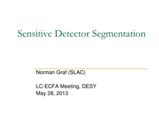
Binary Segmentation Results DICOM classic (pixel/voxel) segmentation Gray Matter, CSF and Partial Volume White Matter Segment 2 Segment 1 2 Lesion Part 1 Segment 4 Lesion Part 2 Segment 3 3 4 Modality = SEG Derived image object using enhanced multi-frame image paradigm Multiple segments per object, each having a property (categorization) Segments linked to one or more frames, pixels show presence of property at pixel location Two disparate methods in single SOP Class planar and volumetric 6
Planar (pixel) segmentation For segmentation of projection or other single plane images Possibly including each slice in a CT or MR volume (multi- frame, or series of single frames) Indicated by absence of Frame of Reference UID Each segmentation frame references its corresponding source single frame AKA derivation image Segmentation frame pixels are 1:1 with source Same pixel matrix size, spacing 7
Volumetric (voxel) segmentation Segmentation object uses same Frame of Reference as source image(s) Extent of SEG frames may differ from extent of source, may use different spatial resolution, different orientation Frame location in Frame of Reference specified by Pixel Measures, Plane Position (Patient), and Plane Orientation (Patient) functional groups Segmented volume identified by Frame of Reference UID may correspond to multiple single frame objects in a source series E.g., for classical CT or MR SOP Instances Single Segmentation object may reference such multiple source images Note: similar approach NOT used in Heightmap Segmentation 8
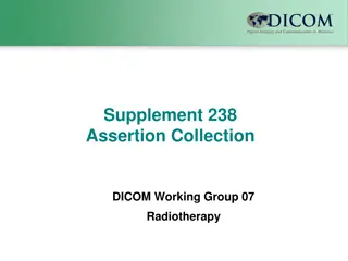
Segmentation data structure Binary Segmentation Results Gray Matter, CSF and Partial Volume Other attributes White Matter Segment 2 Segment 1 Segment Sequence 2 Item 1 (Segment 1) Segment Number = 1 Shared Functional Groups Sequence Segment Name = White Matter Item 1 (Shared all frames) Derivation Image Sequence Segment Category = Brain Lesion Part 1 Segment 4 Lesion Part 2 Segment 3 Segment Type = White Matter 3 4 Item 1 Item 2 (Segment 2) Segment Number = 2 Reference to source image (external object) Segment Name = Grey Matter Per-frame Functional Groups Sequence Item 1 (Frame 1) Segment Identification Sequence Segment Category = Brain Segment Type = Grey Matter Item 1 Item 3 (Segment 3) Segment Number = 3 Segment Sequence: Catalog of properties Referenced Segment Number = 1 Segment Name = Lesion Part 1 Segment Category = Brain Item 2 (Frame 2) Segment Identification Sequence Segment Type = Lesion Item 4 (Segment 4) Segment Number = 4 Item 1 Referenced Segment Number = 2 Functional Group Sequence: Attributes and classification of each frame Segment Name = Lesion Part 2 Pixel Data Segment Category = Brain Item 3 (Frame 3) Frame 1 Segment Type = Lesion Segment Identification Sequence Pixel Data: Stream of multiple frames Item 1 Frame 2 Referenced Segment Number = 3 Frame 3 Item 4 (Frame 4) Segment Identification Sequence Frame 4 Item 1 9 Referenced Segment Number = 4
Segment Sequence (0062,0002) Catalog of segmentation properties Identifier, label, description Algorithm used Property category (e.g., anatomy, physical object, functional locus) - CID 7150 Specific property (e.g., liver, pacemaker, perfusion) CID 7151 Preferred display color 10
Heightmap segmentation Locates a surface intersecting an image plane or volume by its height (distance) from a baseline Reuses planar segmentation data mechanism Enhanced multi-frame image paradigm Multiple segments per object, each having a property Each segmentation frame references its corresponding source Pixel spacing is 1:1 with source 11
Derivation (Source) Image Heightmap is specified in the volumetric space (Frame of Reference) of referenced Derivation Image(s) Identified in Derivation Image Functional Group Derivation Code Sequence (113076, DCM, "Segmentation"); Purpose of Reference (121322, DCM, "Source Image for Image Processing Operation") For consistency with Segmentation IOD planar segmentation codes 12
2D and 1D Heightmaps Heightmap for a 3D volume is a 2D plane Heightmap for a 2D plane is a 1D raster (row) Heightmap Segmentation IOD supports 1D or 2D frames Heightmap follows DICOM convention of measuring pixel offsets from top of frame (TLHC) 13
Heightmap segmentation 1D frame Each Heightmap 1D frame is one row with number of columns the same as corresponding source (Derivation Image) frame Heightmap stored pixel values represent distance from top in source image in units of pixel rows (sub-pixel resolution) Upper edge of top pixel is 0.0, center of top pixel is 0.5 columns in both Derivation Image and Heightmap top center of top pixel in column (heightmap value 0.0) center of top pixel in column (heightmap value 0.5) heightmap value (fractional vertical pixels in Derivation Image) bottom center of top pixel in column (heightmap value 1.0) rows in Derivation Image bottom center of last pixel in column (heightmap value equals # rows in Derivation Image) 14
Heightmap 1D frames for various OPT scan patterns Multi-frame Ophthalmic Tomography (OPT) image may have b-scans at varying plane orientations E.g., radial scan pattern, circular scan pattern One Heightmap 1D frame for each segmented layer in each source b-scan frame 4 1 2 5 3 6 2 1 4 3 5 6 OPT radial scan frame orientations relative to OP retinal image 15
Heightmap 2D frames for volumetric OPT scan patterns OPT image may have b-scans at constant plane orientation and regular plane spacing E.g., cube scan pattern One Heightmap 2D frame for each segmented layer covers all source B-scan frames Pixel Data same as stream of 1D Heightmap rows for each source frame Column spacing same as source column spacing, row spacing same as source frame spacing 16 heightmap 2D frame values rendered as offsets into a 3D volume
Heightmap 2D frame pixel values rendered as offsets into a Derivation Image 3D volume Heightmap columns Heightmap rows Derivation Image rows Derivation Image frames Derivation Image columns 17
Heightmap pixel matrix spacing based on Derivation Image spacing Heightmap segmentation Heightmap row spacing equals Derivation image frame spacing Heightmap column spacing equals Derivation image column spacing (x1,y1,z1) (x2,y2,z2) Derivation image frame spacing derived from differences in Image Position (Patient) Derivation image 18 Derivation image column spacing
2D Heightmap Frame Row Spacing Equal to slice spacing in referenced derivation image Spacing Between Slices (0018,0088) might not be present in OPT images Slice Thickness (0018,0050) is technically an incorrect substitute even though it is commonly used as it is a required attribute Correctly should be computed from differences in Image Position (Patient) (0020,0032) in referenced Derivation Image 19
Heightmap position and orientation based on Derivation Image Heightmap segmentation HR = (cos R,cos R,cos R) (x,y,z) Heightmap plane position (x,y,z) equals Derivation image 1st plane position (x1,y1,z1) HC = (cos C,cos C,cos C) Heightmap plane row orientation HR equals Derivation image plane row orientation DR DR =(cos R,cos R,cos R) (x1,y1,z1) DC = (cos C,cos C,cos C) Heightmap plane column orientation HC equals cross product of Derivation image plane column orientation and row orientation DC X DR 20 Derivation image
Referenced images Heightmap is specified in the volumetric space (Frame of Reference) of a referenced Derivation Image Identified in Derivation Image Functional Group Frame of Reference Coordinate System may be deformed see CP2347 Clarify OPT Frame of Reference Coordinate System Heightmap may be computed from a different object (e.g., Raw Data) identified in Referenced Image Functional Group 21
OPT Acquisition and Display Frame of Reference Coordinate System Typical 6x6mm scan area Deformation is small, and measurements in image are corrected by (proprietary) algorithms CP2347 clarifies that it is nominally in the Patient- based Coordinate System, with caveat for possible deformation Heightmap follows OPT frame location in space and coordinate system, including for circular or other non-linear scans 22
N::M Relationship between OPT and SEG Instances Heightmap SOP Instance can record multiple layers (segments) One Heightmap SOP Instance can be applied to multiple OPT SOP Instances (e.g., if OPTs are one frame per instance) All OPTs (and Heightmap) must have same Frame of Reference UID Multiple Heightmap SOP Instances can be applied to single OPT SOP Instances (e.g., one layer per Heightmap instance) 23
Pixel Values Heightmap pixel data values use 32-bit floating point VR for sub-pixel resolution of position in anatomic image Absence of segment in a column indicated by value in range specified by Float Pixel Padding Value (0028,0122) and Float Pixel Padding Range Limit (0028,0124) CP2352 in process to clarify whether IEEE 754 NaN (Not a Number) values are legal (e.g., for padding) 24
Use in non-OPT contexts Initial use case for segmenting retinal layers in OPT No ophthalmic-specific vocabulary or constructs Major constraint is geometric assumptions Derivation image frames perpendicular to heightmap baseline plane Rows of heightmap data correspond to the top rows of Derivation Image frames Columns of the Heightmap Segmentation correspond to the frames of the Derivation Image 25
Heightmap in En Face Image Ophthalmic OCT En Face Image presents a cross-sectional slab of OPT or OPT Volume Analysis multi-frame image as a planar image A surface of the slab may be specified using one segmented surface, or an interpolation of two segmented surfaces, or a fixed offset above/below a segmented surface Revision of En Face IOD allows segmented surface to be Heightmap, Surface Segmentation, or any other SOP Class Previously, En Face IOD allowed only Surface Segmentation Purpose is to show traceability, not to enable receiving app to reproduce slab 26
Relationship of OCT-A related SOP Instances Ophth OCT En Face Image SOP Instance Source Image Source Image Frame Location Referenced Image Referenced Segmentation Ophth OCT B-Scan Volume Analysis SOP Instance Frame Location Referenced Image Derivation Image [Heightmap, Surface] Segmentation SOP Instance Derivation Image OPT Image SOP Instance (structural) Frame Location Referenced Image Derivation Image same Frame of Reference Raw Data SOP Instance Ophth Photography Image SOP Instance (localizer) 27
Non-Backward Compatible Changes to En Face Image IOD Allowing segmentation other than Surface Segmentation SOP Class General change to segmentation object references Adding mandatory reference to localizer (ophthalmic photography) image 28


")

 segmentation")

")

 Image")