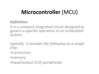
Understanding Interrupts in 8051 Microcontroller
Interrupts in 8051 microcontrollers allow the system to respond to asynchronous events while multitasking on a single CPU, giving the illusion of handling many things simultaneously. They introduce the concept of priority, enabling preference over simultaneous interrupts. The interrupt vectors determine the address of the Interrupt Service Routine (ISR) when a specific interrupt occurs, allowing the system to efficiently handle external or internal events. When an interrupt is activated, the 8051 quickly saves the current status, jumps to the corresponding location in the interrupt vector table, and executes the ISR before returning to the main program flow.

Download Presentation

Please find below an Image/Link to download the presentation.
The content on the website is provided AS IS for your information and personal use only. It may not be sold, licensed, or shared on other websites without obtaining consent from the author. Download presentation by click this link. If you encounter any issues during the download, it is possible that the publisher has removed the file from their server.
E N D
Presentation Transcript
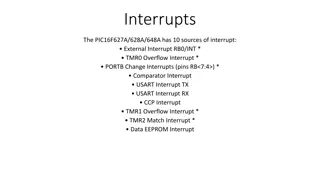
An interrupt is the occurrence of a condition event Interrupts allow a system to respond to asynchronous handle the events while another task is running An interrupt driven system many things simultaneously (multitasking on one CPU) The routine that deal s with a specific interrupt is called an Interrupt Service Routine (ISR interrupt handler An interrupt is the occurrence of a condition an event - - which interrupts normal program flow an which interrupts normal program flow asynchronous events (not in program flow) and interrupt driven system gives the illusion of doing ISR) or an interrupt handler Interrupts routines are activated by the occurrence of either an external Interrupt routines are said to run in the background while the main system program runs in the foreground external or an internal internal event (a.k.a. exceptions exceptions) background foreground 2
Interrupts allow the 8051 to respond to asynchronous events (external or internal) only when required. o The alternative is called polling testing status bits - which can be time consuming, wasting precious CPU resources/cycles Interrupts introduce the concept of priority is given preference over another simultaneous interrupt Interrupt Vectors particular interrupt occurs? 8051 Interrupt Vector Table priority where one interrupt Interrupt Vectors--where is the address of the ISR address of the ISR when a only when interrupts are enabled only when interrupts are enabled 8051 Interrupt Vector Table (Atmel 89C51RD2 has 3 more not covered) Interrupt Vector Address Number Bytes Pin Flag Clearing Comment Reset 0000H 3 Auto Power-on INT0 0003H 8 P3.2 Auto External Hardware TF0 000BH 8 Auto Timer 0 INT1 0013H 8 P3.3 Auto External Hardware TF1 001BH 8 Auto Timer 1 RI/TI 0023H 8 Programmer Serial Communication TF2/EXF2 002Bh 3 Programmer Each has 2 possible reasons for interrupt Timer 2 Each has 2 possible reasons for interrupt 3
When an interrupt is activated the 8051 Finishes the instruction currently being executed Saves the current status of all the interrupts and stores the current PC Stack Vectors (i.e. jumps) to the corresponding location within the interrupt vector table, i.e. PC Vector Table address Option 1: If the ISR fits in the available space you can immediately service the interrupt Option 2: If the ISR is too large then the vector table contains a long jump (ljmp) to the Interrupt Service Routing (ISR) The last instruction of the ISR is a reti Responsibility of ISR to save/restore any registers that it uses, including the PSW to/from the stack for the reti When an interrupt is activated the 8051 reti (Return from Interrupt) PSW, having the same number of pushes and pops reti instruction to work correctly Original PC is popped off the stack returning to where program was when the interrupt occurred 4
All interrupts are disabled (masked) at system reset Software enables those interrupts required IE IE (A8h) I Interrupt E Enable SFR is used to enable/disable interrupts 7 6 5 4 3 2 1 0 EA -- ET2 ES ET1 EX1 ET0 EX0 EA - IE.6 ET2 IE.5 ES IE.4 ET1 IE.3 EX1 IE.2 ET0 IE.1 EX0 IE.0 EA Global enable If EA = 1, each interrupt source is individually enabled or disabled by setting or clearing its enable bit Not implemented. Don t set. Enables/disables Timer 2 TF2 or EXF2 interrupt (8052) Enables/disables Serial Port RI or TI interrupt Enables/disables Timer 1 overflow interrupt Enables/disables External interrupt 1 Enables/disables Timer 0 overflow interrupt Enables/disables External interrupt 0 Global enable. If EA = 0, no interrupt is acknowledged. IE.7 5
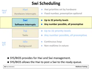
Each interrupt source is individually programmed as being a high or low priority interrupt Prioritized allows resolution of simultaneous Prioritized interrupts allow for preemptive IP IP (B8h) I Interrupt P Priority SFR Priority is either high (1) or low (0) If an ISR is active and a higher priority interrupt occurs, it is interrupted (i.e. preempted). A high level ISR can not be interrupted. Each interrupt source is individually programmed as being a high or low priority interrupt simultaneous interrupts preemptive interrupt handlers -- -- PT2 PS PT1 PX1 PT0 PX0 IP.7 IP.6 IP.5 IP.4 IP.3 IP.2 IP.1 IP.0 Undefined Undefined Priority for Timer 2 interrupt Priority for serial port interrupt Priority for Timer 1 interrupt Priority for external 1 interrupt Priority for Timer 0 interrupt Priority for external 0 interrupt 6
Each interrupt source is individually programmed to one of four priority levels IPH IPL Priority from highest to lowest (3,2,1,0) If an ISR is active and a higher priority interrupt occurs, it is interrupted. A higher level ISR can not be interrupted. Equal priorities yield to polling sequence (cf. page 75, AT8951RD2 spec) Each interrupt source is individually programmed to one of four priority levels (00, 01, 10, 11) IPH (B7h) Interrupt Priority HIGH IPL (B8h) Interrupt Priority LOW -- IP (H/L). 7 Undefined -- IP (H/L). 6 PCA (Programmable Counter Array) PT2 IP (H/L). 5 Priority for Timer 2 interrupt PS IP (H/L). 4 Priority for serial port interrupt PT1 IP (H/L). 3 Priority for Timer 1 interrupt PX1 IP (H/L). 2 Priority for external 1 interrupt PT0 IP (H/L). 1 Priority for Timer 0 interrupt PX0 IP (H/L). 0 Priority for external 0 interrupt 8
8051 has two external interrupts: INT0 and INT1 Tied to external pins: INT0 (P3.2), INT1 (P3.3) P3.2 and P3.3 are general purpose I/O pins until the respective Interrupt Enable bits are set (i.e. EX0 and EX1, respectively) Activation of external interrupts 8051 external interrupts activated in one of two ways (1) Level-triggered of (2) edge-triggered TCON.0 (IT0) and TCON.2 (IT1) defines interrupt type IT0/IT1 = 0 for level-triggered interrupts (default) IT0/IT1 = 1 for edge triggered interrupts 8051 has two external interrupts: INT0 and INT1 Activation of external interrupts Vcc 7 6 5 4 3 2 1 0 TR1 TR0 IT1 TF1 IT0 TF0 IE1 IE0 INT1 Pull-up TCON (88h) 8051 9
Level INT0/INT1 held normally HIGH. A LOW level on one of these signals will trigger the respective interrupt The 8051 keeps sampling INTn for a LOW once each machine cycle Some 8051 s specify that the pin must be held in a LOW state until the start of the execution of the ISR. If the INTn pin is brought back to a HIGH before the start of the ISR, there will be no interrupt. Thus, to ensure activation of an external interrupt, it must remain LOW for at least 4 machine cycles Level- -triggered interrupts triggered interrupts The LOW on the pin must be removed before the last instruction in the ISR (reti) is executed else another interrupt will occur 10
Edge Setting IT1 or IT0 to 1 programs the 8051 to detect edge-triggered signals Edge- -triggered interrupts triggered interrupts INT1/INT0 held normally HIGH. A HIGH-to-LOW transition on one of these signals will trigger the respective interrupt In edge-triggered interrupts, the INT1/INT0 signal must be held HIGH for at least one machine cycle, and then held LOW for at least one machine cycle to ensure that the transition is seen by the 8051 The 8051 automatically sets the respective External Interrupt Edge Flag (IE1/IE0) in the TCON register when using edge-trigerring Regarding the Interrupt Type bits (IT1/IT0) in the TCON register, the following two points must be emphasized: Upon execution of a RETI instruction, the respective IEn bit will be cleared automatically, indicating the edge-triggered interrupt has been serviced While the ISR is being executed, the 8051 ignores all transitions on the external interrupt signals INT1/INT0 7 6 5 4 3 2 1 0 TR1 TCON (88h) TR0 TF1 IT1 IT0 TF0 IE1 IE0 11
TCON (88h) Bit Symbol TCON.7 TF1 TCON.6 TR1 TCON.5 TF0 TCON.4 TR0 TCON.3 IE1 TCON.2 IT1 TCON.1 IE0 TCON.0 IT0 TCON (88h) Comment T1 Overflow Flag T1 Run Control (1=ON, 0=OFF) T0 Overflow Flag T1 Run Control (1=ON, 0=OFF) EI1 edge flag. SET on H2L transition. Cleared by CPU I1 type control. 1=falling edge,0=low-level activated EI0 edge flag. SET on H2L transition. Cleared by CPU I0 type control. 1=falling edge,0=low-level activated Edge IE0/IE1 automatically cleared when CPU vectors to interrupt Level be de-activated before the ISR is completed. Usually the ISR acknowledges the interrupt and the interrupting device removes the interrupt request External Interrupts are sampled once each machine cycle so input should be held for at least 12 oscillator periods to ensure proper sampling Edge- -detect: detect: the input must be held HIGH for one cycle and LOW for another. Level- -activated: activated: the input must be held until interrupt generated. Must also 12
TI (Transmit Interrupt) is set when the last bit of framed data, the stop bit, is transmitted indicating that SBUF empty and ready for another byte RI is correctly received indicating that SBUF ready to be read Behavior of TI or using interrupts. Difference is how we detect and respond to its occurrence TI User must determine which is the source in the ISR Typical use relies on RI TI Analogous to receiving and generating a phone call TI SBUF is RI (Receive Interrupt) is set when an entire frame of data SBUF now has a byte TI and RI RI is the same whether we are polling TI and RI RI are OR d to generate a single interrupt RI for data received but will poll TI to ensure data sent Always clear TI TI or RI RI prior to execution of reti 13


 at system reset")


")
 is set when the last bit of framed")