Overview of Intel 8086 Microprocessor and Internal Architecture
Intel 8086 microprocessor is a vital component in electronics, with an internal architecture comprising BIU and EU. The BIU handles bus operations, instruction fetching, and address calculation, while the EU executes instructions from the instruction queue. The pin diagram and internal architecture illustrate the various components and signals used in the operation of the 8086 microprocessor.

Download Presentation

Please find below an Image/Link to download the presentation.
The content on the website is provided AS IS for your information and personal use only. It may not be sold, licensed, or shared on other websites without obtaining consent from the author. Download presentation by click this link. If you encounter any issues during the download, it is possible that the publisher has removed the file from their server.
E N D
Presentation Transcript
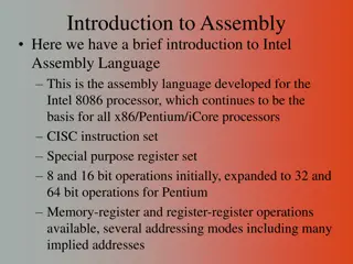
Introduction to 8086 mp By: Ms. ZEENATH Asst.Prof Dept. Of ECE
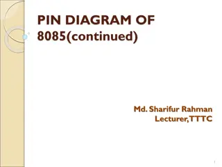
Pin Diagram of 8086 GND AD14 AD AD 40 39 38 37 36 35 34 33 32 VCC AD15 A16 /S3 A17/ S4 1 2 3 4 5 6 7 8 13 12 A18/ S5 AD AD 11 A /S 19 _____ BHE / S7 6 10 AD AD AD7 AD AD ____ 9 8086 MN/MX 8 ___ RD ___ _____ RQ / GT ( HLDA) 1 9 10 11 12 _____ _____ RQ / GT ( HOLD) 0 CPU 6 31 5 30 AD4 AD3 AD2 AD AD _______ LOCK ___ (WR) ____ 29 28 27 26 25 ____ S2 13 (M / IO ) ___ ___ S1 ___ S0 (DT / R) 14 15 _____ (DEN) ________ 1 QS0 (ALE) 16 17 18 19 0 NMI QS (INTA) 1 24 ______ TEST INTR 23 22 CLK READY GND 20 21 RESET MM/M1/LU3/V1/2004 5
VCC GND A0- A15, A16/ S A /S 3 19 6 INTR _____ INTA ADDRESS / DATA BUS INTERRUPT ______ TEST INTERFACE D - D 0 15 NMI 8086 ALE ___ MPU RESET BHE / S7 __ M / IO MEMORY I / O CONTROLS __ DT / R HOLD ____ RD DMA INTERFACE _____ WR HLDA VCC _____ DEN MODE SELECT ____ READY MN / MX CLK MM/M1/LU3/V1/2004 6
Internal Architecture of 8086 8086 has two blocks BIU and EU. The BIU performs all bus operations such as instruction fetching, reading and writing operands for memory and calculating the addresses of the memory operands. The instruction bytes are transferred to the instruction queue. EU executes instructions from the instruction system byte queue.
Internal Architecture of 8086 (cont..) COMMON SIGNALS COMMON SIGNALS Name Function Type Bidirectional 3-state Output 3 - State Output 3 - State AD AD 15 S6 A AD AD 15 / S 19 Address/ Data Bus Address/ Data Bus 0 0 3-state A 6 A /S / Address / Status 16 3 Bus High Enable / Status Minimum / Maximum Mode Control Read Control / Output 3- State Input Input Output 3- State BHE BHE / S 7 / S 7 Status MN / MX MN / MX / RD RD Output 3 - State Output 3- State TEST TEST Wait On Test Control Wait On Test Control Input Input READY READY Wait State Controls Wait State Controls Input Input RESET RESET System Reset - Input Input System Reset Maskable Interrupt Request Interrupt Request System Clock + 5 V Ground Non NMI NMI Input Input Input Input Input INTR CLK Vcc GND INTR CLK Vcc Input
Internal Architecture of 8086 (cont..) Minimum Mode Signals ( MN / MX = Vcc ) ( / = ) Name Function Type HOLD Hold Request Input HLDA HLDA Output Hold Acknowledge Output , 3- s t a t e - , WR Write Control Write Control M/ I O M/ I O Output, 3- S t a t e - , Memory or IO Control Output , 3-S t a t e 3- S t a t e , Data Transmit / DT/R DT/R Receiver Output , 3- State 3- State , Date Enable DEN DEN Address Latch Enable Output ALE ALE Output INTA INTA Interrupt Acknowledge
Internal Architecture of 8086 (cont..) Maximum mode signals ( MN / MX = GND ) Name Function Request / Grant Bus Access Control Type Bidirectional RQ / GT1, 0 Output, 3- State LOCK Bus Priority Lock Control Output, 3- State Bus Cycle Status S S 2 0 Output QS1, QS0 Instruction Queue Status
Minimum Mode Interface When the Minimum mode operation is selected, the 8086 provides all control signals needed to implement the memory and I/O interface. The minimum mode signal can be divided into the following basic groups : address/data bus, status, control, interrupt and DMA. Address/Data Bus : these lines serve two functions. As an address bus is 20 bits long and consists of signal lines A through A . A 19 address gives the 8086 a 1Mbyte memory address space. More over it has an independent I/O address space which is 64K bytes in length. 0 19represents the MSB and A LSB. A 20bit 0
Minimum Mode Interface ( cont..) Vcc GND INTR A -A ,A /S A /S 0 15 16 3 19 6 INTA Interrupt interface Address / data bus TEST D D 0 15 NMI 8086 ALE RESET MPU BHE / S7 M / IO Memory I/O controls HOLD DMA interface DT / R RD HLDA WR Vcc DEN Mode select READY MN / MX CLK clock Block Diagram of the Minimum Mode 8086 MPU
Minimum Mode Interface ( cont..) S4 S3 Segment Register Extra 0 0 1 Stack 0 Code / none 1 0 Data 1 1 Memory segment status codes.
Maximum Mode Interface When the 8086 is set for the maximum-mode configuration, it provides signals for implementing a multiprocessor / coprocessor system environment. By multiprocessor environment we mean that one microprocessor exists in the system and that each processor is executing its own program. Usually in this type of system environment, there are some system resources that are common to all processors. They are called as global resources. There are also other resources that are assigned to specific processors. These are known as local or private resources.
INIT Multi Bus S0 S S LOCK BUSY CBRQ 1 BPRO 8289 Bus arbiter 2 BPRN CRQLCK RESB SYSB/RESB ANYREQ BREQ CLK Vcc GND BCLK CLK AEN IOB CLK AEN INTR LOCK IOB S0 MRDC CLK AEN TEST NMI IOB MWTC S1 S S S2 DEN DT/ R ALE AMWC 0 IORC 8288 Bus controller S2 1 RESET IOWC AIOWC INTA MCE / PDEN 8086 MPU DEN DT / R ALE A -A 0 A /S -A /S 16 3 15, 19 6 MN/MX D D 0 15 BHE RD READY QS , QS 1 0 Local bus control 8086 Maximum mode Block Diagram RQ / GT1 RQ / GT0
Minimum Mode 8086 System (cont..) Clk T1 T2 T3 TW T4 ALE BHE ADD / STATUS S7 S3 A A 19 16 Bus reserved for data in A A 15 ADD / DATA D15 D0 0 RD DEN DT / R Read Cycle Timing Diagram for Minimum Mode
Minimum Mode 8086 System (cont..) T1 T2 T3 TW T4 T1 Clk ALE BHE S7 S3 ADD / STATUS A A 19 16 ADD / DATA A A 15 Valid data D15 D0 0 WR DEN DT / R Write Cycle Timing Diagram for Minimum Mode
Addressing Modes (cont..) Implied - the data value/data address is implicitly associated with the instruction. Register - references the data in a register or in a register pair. Immediate - the data is provided in the instruction. Direct - the instruction operand specifies the memory address where data is located. Register indirect - instruction specifies a register containing an address, where data is located. This addressing mode works with SI, DI, BX and BP registers. Based :- 8-bit or 16-bit instruction operand is added to the contents of a base register (BX or BP), the resulting value is a pointer to location where data resides.
Addressing Modes Indexed :- 8-bit or 16-bit instruction operand is added to the contents of an index register (SI or DI), the resulting value is a pointer to location where data resides. Based Indexed :- the contents of a base register (BX or BP) is added to the contents of an index register (SI or DI), the resulting value is a pointer to location where data resides. Based Indexed with displacement :- 8-bit or 16-bit instruction operand is added to the contents of a base register (BX or BP) and index register (SI or DI), the resulting value is a pointer to location where data resides.
Interrupts (cont..) The processor has the following interrupts: INTR is a maskable hardware interrupt. The interrupt can be enabled/disable. When an interrupt occurs, the processor stores FLAGS register into stack, disables further interrupts, fetches from the bus one byte representing interrupt type, and jumps to interrupt processing routine address of which is stored in location 4 * <interrupt type>. Interrupt processing routine should return with the IRET instruction.
Interrupts (cont..) NMI is a non-maskable interrupt. Interrupt is processed in the same way as the INTR interrupt. Software interrupts can be caused by: INT instruction - breakpoint interrupt. This is a type 3 interrupt. INT <interrupt number> instruction - any one interrupt from available 256 interrupts. INTO instruction - interrupt on overflow
Interrupts Single-step interrupt - generated if the TF flag is set. This is a type 1 interrupt. When the CPU processes this interrupt it clears TF flag before calling the interrupt processing routine. Processor exceptions: Divide Error (Type 0), Unused Opcode (type 6) and Escape opcode (type 7). Software interrupt processing is the same as for the hardware interrupts.


")
")
")

")
")


")
")
")

")
")