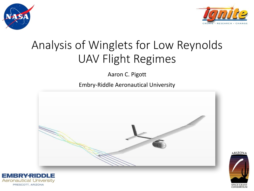
Analysis of Winglets for Low Reynolds UAV Flight Regimes
This study focuses on the analysis and optimization of winglets for low Reynolds number Unmanned Aerial Vehicles (UAVs). It covers the importance of winglets in reducing induced drag, the design considerations, meshing models, and the results obtained. The research aims to enhance the performance and efficiency of UAVs through winglet design variations.

Download Presentation

Please find below an Image/Link to download the presentation.
The content on the website is provided AS IS for your information and personal use only. It may not be sold, licensed, or shared on other websites without obtaining consent from the author. Download presentation by click this link. If you encounter any issues during the download, it is possible that the publisher has removed the file from their server.
E N D
Presentation Transcript
Analysis of Winglets for Low Reynolds UAV Flight Regimes Aaron C. Pigott Embry-Riddle Aeronautical University
Introduction and Overview Introduction Goal: Optimization of winglet sweep using STAR-CCM+ Overview Boeing AerosPACE UAV Design Why Winglets? Winglet Design The Mesh The Physics Results Conclusion
Boeing AerosPACE Collaborative senior design project with Boeing, Brigham Young University, Embry-Riddle Aeronautical University, Georgia Institute of Technology, Purdue University, and Tuskegee University Objective: Successfully collaborate and design a hand-launchable Search and Rescue UAV Winglet Analysis performed on Boeing AerosPACE UAV
UAV Design Length: 58.5 in. Span: 92.8 in. AR: 9 Main Wing Chord: 11.4 in
Why Winglets? Wingtip vortices cause induced drag Induced drag reduces aircraft range and endurance Winglets minimize wingtip vortices
Winglet Design P. Panagiotou, P. Kaparos, and K. Yakinthos found that a winglet with 50 cant angle is optimum at Re 1.2 million This study uses 50 cant angle and varies sweep of winglet
Winglet Design Baseline: Schumann Tips Case 1: No Winglet Case 2: 30 Sweep Case 3: 45 Sweep Case 4: 60 Sweep Case 2, 3, and 4: 50 degree cant angle 11.4 inches tall (equal to wing chord) 0 toe and 0 twist angle
Mesh Independence Study Incrementally changed base size to ensure solution was mesh-independent 7 million cell mesh selected based on results
Meshing Models Mesh Base Size: .009m Mesh Size: 7 million cells Prism Layer Mesher Prism Layer Thickness: .007m Prism Layer Stretching: 1.2 Surface Remesher Trimmer
Physics Models Steady Constant Density Segregated Flow K-Omega Turbulence Air conditions in Prescott, AZ to compare to wind tunnel data
Wind Tunnel A wind tunnel model was used to verify CLand CD data for the baseline model Wind Tunnel vs. CFD Data Here
Conclusion Schumann tips reduced induced drag cause by wingtip vortices. CL/CDincreased at each AOA Variable wingtip conclusion here
Acknowledgements Dr. Shigeo Hayashibara, ERAU Joe Becar, Brigham Young University Boeing AerosPACE Program