MDP Technical Meeting #5 on 20 T Hybrid Magnet and Comparative Analysis
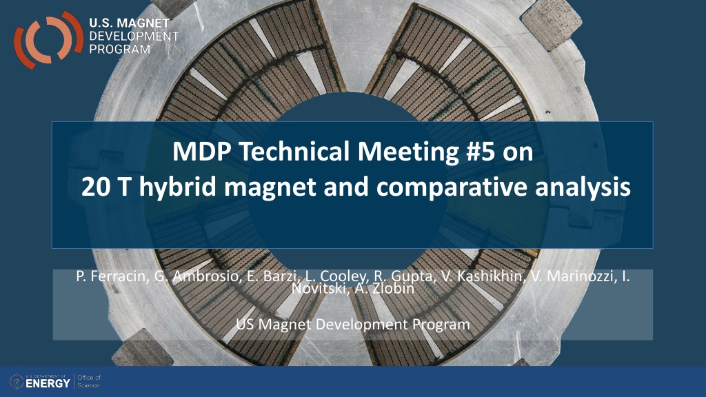
The MDP Technical Meeting #5 focuses on the conceptual design and comparative analysis of a 20 T hybrid HTS-LTS magnet. Goals include defining design criteria, exploring different design options, stress management techniques, and integrating LTS/HTS technologies. The working group aims to provide inputs for refining roadmaps and directions for magnet development. The comparison aims to evaluate various design concepts based on objective criteria. Modeling efforts will include classical 2D/3D mechanical, magnetic, and QH simulations from 2020 to 2023.

Download Presentation

Please find below an Image/Link to download the presentation.
The content on the website is provided AS IS for your information and personal use only. It may not be sold, licensed, or shared on other websites without obtaining consent from the author. Download presentation by click this link. If you encounter any issues during the download, it is possible that the publisher has removed the file from their server.
E N D
Presentation Transcript
MDP Technical Meeting #5 on 20 T hybrid magnet and comparative analysis P. Ferracin, G. Ambrosio, E. Barzi, L. Cooley, R. Gupta, V. Kashikhin, V. Marinozzi, I. Novitski, A. Zlobin US Magnet Development Program
Outline Definition of the goals of the working group Design criteria for a 20 T hybrid magnet Some preliminary estimates of radiuses and dimensions Overview of current hybrid work Action items 4/28/2020 P. Ferracin -- 20 T hybrid and comparative analysis 2
1st goal of the working group Conceptual design of a 20 T hybrid HTS-LTS magnet Comparative analysis of different design options for a 20 T hybrid Cos design and its stress-management options Traditional Cos Canted Cos (CCT) Stress management Cos (SMCT) Block-type coil design (block with flared ends) Common-coil design (block with racetrack coil) Definition of general design criteria: aperture, field, margin .. Analysis of challenges specifically of hybrid magnets Integration of LTS/HTS, mechanics, protection, powering, diagnostics, test facility .. 4/28/2020 P. Ferracin -- 20 T hybrid and comparative analysis 3
1st goal of the working group An example: 16 T dipole magnets for FCC Ideally the goal should be to carried out the full 2D design and analysis of a 20 T hybrid for all the design options considered Cos design and its stress-management options, Block-type design, Common-coil design In addition, 3D considerations will be included in the comparison 4/28/2020 P. Ferracin -- 20 T hybrid and comparative analysis 4
5 1st goal of the working group The goal of the comparison should not be, or does not necessarily have to be reaching a consensus on a particular design Instead, more realistically, the working group could aim at Discussing and reviewing the different designs and listing pluses and minuses or open issues .grounding on objective criteria Providing inputs to the other areas (in particular area I and area II) to better define their roadmaps and overall directions, and avoid inconsistencies Comparative analysis of magnet design concepts
1st goal of the working group Time frame: 2020 2023 Methods Modeling effort classical 2D/3D mechanical, magnetic and QH simulations Developing new modeling techniques is not part of this task However, if new tool/analysis is required feed-back to Technology area (III), modeling and simulations 4/28/2020 P. Ferracin -- 20 T hybrid and comparative analysis 6
2nd goal of the working group Review and follow-up of current work towards 9-15 T hybrid magnets This current work can be divided based on the field level 9-10 T 11-12 T 13-14 T Beyond 15 T The goal is to collect and organize information from these programs (responsibility of area I and area II) to provide inputs for 20 T hybrid design 4/28/2020 P. Ferracin -- 20 T hybrid and comparative analysis 7
Outline Definition of the goals of the working group Design criteria for a 20 T hybrid magnet Some preliminary estimates of radiuses and dimensions Overview of current hybrid work Action items 4/28/2020 P. Ferracin -- 20 T hybrid and comparative analysis 8
1.Geometrical Magnet total length Magnet straight section Free coil aperture Maximum magnet OD (reference number) ..914 mm (LBNL/4.5K) 2.Conductor Strand diameter Cu:nonCu ratio Non Cu Jc(16T,4.2 K) RRR Reference Jc(B,T) fit Ic degradation due to cabling Maximum number of strands in cable 3.Operational Reference temperature Nominal operation field Margin on the load-line @ 1.9K Geometrical field harmonics at Rref=17 mm Target design field Maximum coil stress Maximum coil-pole separation @ 17 T 4.Quench protection Maximum hot spot temperature Total time delay Maximum voltage to ground @ quench Ground insulation design voltage 5.Reference Jc(B,T) fit: ?c2 ? = ?c201 ?1.52, ?c=?(?) where ?=?/?c0; ?=?p/?c2 (?), Bp is the conductor peak field, Tc0= 16 K, Bc20 =29.4 T, C0= 270 T.kA/mm2. 6.Each magnet concept should provide Description of magnet design including o Strand, cable and insulation (before and after reaction) o Coil cross-section (number of layers, number of turns, conductor weight/m/aperture) o Coil end design concept o Magnet support structure including transverse and axial support o Quench protection system in the case of no energy extraction Maximum magnet bore field Bmax at conductor SSL for 1.9 K and 4.5 K Dependence of Bmax on conductor Jc(16T,4.2K) Calculated geometrical field harmonics, coil magnetization and iron saturation effects in magnet straight section at Rref=17 mm for B=1-16 T Stress distribution in coil and structure at room and operation temperatures and at the nominal (16 T) and design (17 T) fields Coil-pole interface (gap) at the nominal (16 T) and design (17 T) fields Coil maximum temperature and coil-to-ground voltage during quench w/o energy extraction Cost reduction opportunities <2 m >200 mm 50 mm 620 mm (FNAL/1.9K), 660 mm (BNL/1.9K), 0.7-1.2 mm 1.0 0.1 1300 A/mm2 >60 see below 5% 42 (FNAL), 60 (LBNL) Design criteria for a 20 T hybrid magnet 1.9 K 16 T 10 % with respect to cable Ic bn<3 for n<10 (magnet straight section) 17 T 180 MPa (150 MPa during assembly) <10 m for cable width <50% Previous work within MDP on a 16 T dipole magnet GianLuca Sabbi, Alexander Zlobin, MDP General meeting May 17, 2017 March 23, 2017 https://conferences.lbl.gov/event/82/ 350 K 40 ms 1.0 kV >5 kV v.4 MDP 16 T dipole: Target parameters and specifications 1.Geometrical Magnet total length Magnet straight section Free coil aperture Maximum magnet OD (reference number) ..914 mm (LBNL/4.5K) 2.Conductor Strand diameter Cu:nonCu ratio Non Cu Jc(16T,4.2 K) RRR Reference Jc(B,T) fit Ic degradation due to cabling Maximum number of strands in cable 3.Operational Reference temperature Nominal operation field Margin on the load-line @ 1.9K Geometrical field harmonics at Rref=17 mm Target design field Maximum coil stress Maximum coil-pole separation @ 17 T <2 m >200 mm 50 mm 620 mm (FNAL/1.9K), 660 mm (BNL/1.9K), ?p?0.5(1 ?)2, ? ? = ?0(1 ?1.52)0.96(1 ?2)0.96 0.7-1.2 mm 1.0 0.1 1300 A/mm2 >60 see below 5% 42 (FNAL), 60 (LBNL) 1.9 K 16 T 10 % with respect to cable Ic bn<3 for n<10 (magnet straight section) 17 T 180 MPa (150 MPa during assembly) <10 m for cable width <50% 4/28/2020 P. Ferracin -- 20 T hybrid and comparative analysis 9
Design criteria for a 20 T hybrid magnet Geometrical Number of apertures Free coil aperture 1 50 mm Comments The common coils will naturally provide 2 apertures This will be taken into account on the comparison No strong constraints on Magnet total length (<2 m) Magnet straight section (>200 mm) Maximum magnet OD Reference numbers: 620 mm (FNAL/1.9K), 660 mm (BNL/1.9K), 914 mm (LBNL/4.5K) 4/28/2020 P. Ferracin -- 20 T hybrid and comparative analysis 10
Design criteria for a 20 T hybrid magnet Operational Reference temperature 4.5 K optioncan be considered: it would impact the ratio of HTS vs LTS Operational bore field Margin on the load-line @ 1.9K With respect to round strand Ic including self field and 5% cabling degradation Short sample bore field Geometrical harmonics at Rref=17 mm and 20 T: Magnet straight section Target design field 1.9 K 20 T 15 % 23.5 T bn<5 for n<10 20 T 4/28/2020 P. Ferracin -- 20 T hybrid and comparative analysis 11
Design criteria for a 20 T hybrid magnet Operational Maximum Nb3Sn coil stress >180 (<150) MPa at 1.9 (293) K Conditions of coil-pole or rib interfaces at 20 T If bonded Corner spikes (~1 contact element, 1 mm) neglected 20 MPa max. tension If separation allowed: Conditions may be different depending on the design Half cable width in contact or < 50 m max gap 4/28/2020 P. Ferracin -- 20 T hybrid and comparative analysis 12
Design criteria for a 20 T hybrid magnet Bonded vs separation-allowed Test Facility Dipole (by G. Vallone) 4/28/2020 P. Ferracin -- 20 T hybrid and comparative analysis 13
Design criteria for a 20 T hybrid magnet Bonded vs separation-allowed MQXF (by G. Vallone) 4/28/2020 P. Ferracin -- 20 T hybrid and comparative analysis 14
Material limits (by Giorgio Vallone) Superconducting Magnets Material Properties Limits Material / Nb3Sn Coil Titanium Aluminum Bronze Aluminium Magnetic Steel Stainless Steel Details Ref. E at R.T. E at 4.5 K GPa GPa 25 114 110 70 224 210 30 T.C. mm/m MPa 3.8 1.7 3.12 4.2 2 2.8 2.44 sy - RT sy - 4.5 K Rm - R.T. Rm - 4.5 K Elong. MPa MPa KIc - RT MPa m^.5 MPa m^.5 KIc - 4.5 K FAD - 4.5 K Sm - R.T. Sm - 4.5 K MPa 150 692 342 400 175 198 214 17 83 568 / MPa um/m MPa MPa 1, 2, 3 4, 5 25 130 110 79 213 193 0.28 30 0.3 0.3 0.3 0.3 0.3 150 813 473 343 364 508 413 17 83 1189 Grade V 830 410 480 210 238 257 20 100 682 1643 568 490 975 610 496 20 100 1427 900 74 1673 927 650 975 1455 100 58 976 6 7 8 9 9 A7075 Armco SS316LN Parallel to the fibers Normal to the fibers, tension Normal to the fibers, compression 25 25 412 437 286 565 0.3 G10 5.6 5.6 0.3 7.06 Nitronic 40 9 225 210 0.3 2.6 889 1813 Notes and Legend: E R.T. T.C. sy Rm KIc FAD Sm Young Modulus Poisson's coefficient Room Temperature Thermal Contraction Yield Stress Strength Critical SIF, mode I FAD limit Max. allowed stress Safety Factor Crack Size For Ti, Al and Iron we assume a round crack with a constant opening stress applied to it. Stress can be exceeded after a grade IV analysis For materials with no FAD value, the max allowed stress has to be verified against the max. Von Mises eqv. stress (svm) For materials with a FAD value, the max. allowed stress has to be verified against the max between sI and svm Assuming epoxy resin for G10 1.2 1.5 mm References: 1 C. Fichera, IEEE 2019 2 P. Ebermann, SuST 2018 3 B. Bordini, IEEE 2013 4 M. Reytier et al.,Characterization of titanium alloys for cryogenic applications, 2002 5 Matweb 6 Handbook on materials for superconducting machinery, pp. 338 7 CERN and LBNL Measurements 8 CERN Measurements - I. Aviles 9 USPAS 2001, C. L. Goodzeit, Superconducting Accelerator Magnets - An Introduction to Mechanical Design and Construction Methods 4/28/2020 P. Ferracin -- 20 T hybrid and comparative analysis 15
Design criteria for a 20 T hybrid magnet Nb3Sn Conductor and cable Strand diameter Cu:non-Cu ratio Non-Cu Jc round strand with self-field 12 T, 4.2 K 15 T, 4.2 K 16 T, 4.2 K See next slide for reference fit It may be difficult to achieve this in small diameter strands .. RRR (after cabling) Ic degradation due to cabling Maximum number of strands in cable Cable Insulation thickness 0.7-1.2 mm 0.8-2.0 2980 A/mm2 1640 A/mm2 1250 A/mm2 >50 5% 60 0.150 mm 4/28/2020 P. Ferracin -- 20 T hybrid and comparative analysis 16
Design criteria for a 20 T hybrid magnet Nb3Sn Conductor and cable Reference Jc(B,T) fit: ?c2? = ?c201 ?1.52, ?c=? ? where ?=?/?c0; ?=?p/?c2 (?), Bp is the conductor peak field, Tc0= 16 K, Bc20 =29.77 T, C0= 223900 T.A/mm2. ?p?0.5 1 ? 2, ? ? = ?0 1 ?1.520.96 1 ?20.96 Fit of data from recent (03/2020) RRP 108/127, 1.1 mm diameter, 1.1 Cu/non-Cu 4/28/2020 P. Ferracin -- 20 T hybrid and comparative analysis 17
Design criteria for a 20 T hybrid magnet Nb3Sn Conductor and cable 3000 A/mm2 kind of conductor, round, with self field Jc round Jc , 5% deg. Je , 5% deg. 4/28/2020 P. Ferracin -- 20 T hybrid and comparative analysis 18
Design criteria for a 20 T hybrid magnet Nb3Sn Conductor and cable In general, it would be better to stay within already tested parameters (min, max) Magnet SQ01 SQ01 TQ02/LQ TQ03 SMC-11T FNAL 11T CERN 11T HFDC HQ02 HQ01 HD2 DCC017 MQXF FRESCA2/ERMC HFDA01 HEPdipo/TFD Dimension before reaction; In MQXF, assumed expansion during reaction is 4.5 % (th), 1.2 % (w) Strand diameter (mm) Cu/non-Cu ratio Number of strands Bare width (mm) Bare thickness in (mm) Bare thickness out (mm) Bare mid-thickness (mm) Keystone angle 0.7 0.87 20 7.938 0.7 0.97 20 7.884 0.7 0.89 27 10.025 0.7 1.17 27 10.025 0.7 1.25 40 14.700 0.7 1.25 40 14.700 0.7 1.15 40 14.700 0.7 60 21.000 0.778 0.87 35 15.022 0.8 0.87 35 15.150 0.8 0.94 51 21.999 0.8 1.53 30 13.130 0.85 1.20 40 18.150 1 1.30 40 20.900 1 0.92 28 14.230 1.1 1.10 44 26.200 1.280 1.267 1.173 1.173 1.260 1.149 1.149 1.280 1.267 1.347 1.347 1.260 1.351 1.351 1.280 1.267 1.260 1.260 1.260 1.250 1.250 0.00 0.00 1.00 1.00 0.00 0.79 0.79 1.342 1.338 1.406 1.538 1.536 1.406 1.440 1.437 1.406 0.75 0.75 0.00 0.00 0.40 0.00 0.93 0.00 1.462 1.820 1.705 1.950 1.588 1.820 1.935 1.950 1.525 1.820 1.820 1.950 4/28/2020 P. Ferracin -- 20 T hybrid and comparative analysis 19
Design criteria for a 20 T hybrid magnet Bi2212 Conductor and cable (input from T. Shen and L. Garcia Fajardo) The wire diameter: from 0.6 mm to 1.5 mm Cable width: basically same possibilities as with Nb3Sn cables Magnet BIN4/5 LBNL RC coil Strand diameter (mm) 0.8 0.8 Number of strands Bare width (mm) Bare thickness in (mm) Bare thickness out (mm) Bare mid-thickness (mm) Keystone angle 9 4.000 1.500 17 7.800 1.440 1.500 1.440 1.500 1.440 0 0 4/28/2020 P. Ferracin -- 20 T hybrid and comparative analysis 20
Design criteria for a 20 T hybrid magnet Bi2212 Conductor and cable (input from T. Shen and L. Garcia Fajardo) Record performance strand RC5/6 about 20% higher than what is currently comfortably produced. B [T] T 0 1 1.34 3 5 10 15 17.5 20 22.5 25 27.5 30 31.2 I at 100% SSL A 1119 856 800 644 560 474 418 390 370 349 331 314 296 286 Je A/mm2 2226 1703 1592 1281 1114 943 832 776 736 694 659 625 589 569 4/28/2020 P. Ferracin -- 20 T hybrid and comparative analysis 21
Design criteria for a 20 T hybrid magnet REBCO Conductor and cable Maximum Nb3Sn coil stress: <120 MPa (293) K 4/28/2020 P. Ferracin -- 20 T hybrid and comparative analysis 22
Design criteria for a 20 T hybrid magnet Quench protection Maximum hot spot temperature Failure scenarios? Total time delay Maximum voltage to ground @ quench Ground insulation design voltage 350 K >5 kV 40 ms 1.0 kV Powering in series or independent? I would propose in series What about a maximum J in the Cu of 1500 A/mm2 ? It would provide a quick/easy check and limits of the grading options 4/28/2020 P. Ferracin -- 20 T hybrid and comparative analysis 23
Outline Definition of the goals of the working group Design criteria for a 20 T hybrid magnet Some very preliminary estimates of radiuses and dimensions Overview of current hybrid work Action items 4/28/2020 P. Ferracin -- 20 T hybrid and comparative analysis 24
First some references (20 T Bop) 4/28/2020 P. Ferracin -- 20 T hybrid and comparative analysis 25
First some references (towards 20 T) 4/28/2020 P. Ferracin -- 20 T hybrid and comparative analysis 26
Nb3Sn aperture in a 20 T hybrid With properties describe above Nb3Sn and Bi2212 cross at 14.5 T at 4.2 K and 16.5 T at 1.9 K 4/28/2020 P. Ferracin -- 20 T hybrid and comparative analysis 27
Field in at 20 T dipole Bbore_op = 20 T Bpeak_op = Bbore_op 1.04 = 20.8 T Bbore_ss = Bbore_op / 0.85 = 23.5 T Bpeak_ss = Bbore_ss 1.04 = 24.4 T 4/28/2020 P. Ferracin -- 20 T hybrid and comparative analysis 28
Analysis of interface diameter Analytical model from Lucas Brouwer 4/28/2020 P. Ferracin -- 20 T hybrid and comparative analysis 29
Analysis of interface diameter Thick shell with cos distribution Bore field = conductor peak field 4 CCT winding layers, 2 of Bi2212 and 2 of Nb3Sn Field in Nb3Sn is given by self field + stray field from Bi2212 insert From Je to Joverall keeping into account spar and ribs 4/28/2020 P. Ferracin -- 20 T hybrid and comparative analysis 30
Analysis of interface diameter Results: 150-160 mm interface diameter for a 23.5 T magnet 4/28/2020 P. Ferracin -- 20 T hybrid and comparative analysis 31
Analysis of coil radius and thickness Sector coil (60 ) with J = J0distribution 2 0 2 3 1 1 1 J a = + 3 2 3 1 3 1 ln 0 1 Fy a a a 2 12 4 12 a 2 4/28/2020 P. Ferracin -- 20 T hybrid and comparative analysis 32
Analysis of coil radius and thickness 11 T MQXF N strand Strand d (mm) Cable width (mm) Cable in thickn. (mm) Cable out thickn. (mm) Keystone angle Ins under pressure Cu% Sc% Cu/Sc ration Area sc in cable (mm^2) Area copper in cable (mm^2) Area strands in cable (mm^2) Area ins cable (mm^2) Fill fact (Jo/Jc) Je/Jo N strand Strand d (mm) Cable width (mm) Cable in thickn. (mm) Cable out thickn. (mm) Keystone angle Ins under pressure Cu% Sc% Cu/Sc ration Area sc in cable (mm^2) Area copper in cable (mm^2) Area strands in cable (mm^2) Area ins cable (mm^2) Fill fact (Jo/Jc) Jo/Je 40 0.7 14.7 1.149 1.351 0.79 0.1 52.3 47.7 1.10 7.343 8.051 15.394 21.605 0.34 0.71 40 0.85 18.15 1.462 1.588 0.40 0.15 52.3 47.7 1.10 10.827 11.871 22.698 33.671 0.32 0.67 4/28/2020 P. Ferracin -- 20 T hybrid and comparative analysis 33
Veryverypreliminary coil size So, with Jo_op = 385 A/mm2 and Bbore_op = 20 T Coil width ~ 75 mm Very strong assumptions constant uniform Jo, same cable . No spar/ribs 75 mm should a first order thickness of only the cable layers in a cos distribution 4/28/2020 P. Ferracin -- 20 T hybrid and comparative analysis 34
Field in the conductor At short sample, Bp_ss = 24.4 T Je_ss = 670 A/mm2 Jo_ss = 452 A/mm2 So, at 85% of short sample Je_op = 570 A/mm2 Jo_op = 385 A/mm2 4/28/2020 P. Ferracin -- 20 T hybrid and comparative analysis 35
Veryverypreliminary coil size 50 mm aperture Under the previous assumption (very simple analytical model, no stress management .) ID Nb3Sn = 146 mm OD Nb3Sn = 200 mm 75 m total coil thickness 48 mm thick Bi2212 coil 27 mm thick Nb3Sn coil 4/28/2020 P. Ferracin -- 20 T hybrid and comparative analysis 36
Peak stress Stress due to accumulated e.m. forces on the mid-plane No shear, no bending . 4/28/2020 P. Ferracin -- 20 T hybrid and comparative analysis 37
Veryverypreliminary magnet size 20 mm collar 250 mm thick yoke rB ~ t ironB sat 50 mm thick shell Fx/t = 200 MPa OD: 850 mm 4/28/2020 P. Ferracin -- 20 T hybrid and comparative analysis 38
Size comparison LHC MQXF FRESCA2 ???? 4/28/2020 P. Ferracin -- 20 T hybrid and comparative analysis 39
Outline Definition of the goals of the working group Design criteria for a 20 T hybrid magnet Some preliminary estimates of radiuses and dimensions Overview of current hybrid work Both conceptual design and real development Action items 4/28/2020 P. Ferracin -- 20 T hybrid and comparative analysis 40
The 9-10 T field level LBNL Bi2212 insert Bin5c_2 (2-3 T stand alone) in CCT5 (8-9 T) Test planned in 2021 4/28/2020 P. Ferracin -- 20 T hybrid and comparative analysis 41
The 11-12 T field level BNL Coils wound with REBCO tape or CORC (1-3 T) inside DCC017 common coil Nb3Sn dipole (10.2 T) Tape parallel to field Tape perpendicular to field CORC 4/28/2020 P. Ferracin -- 20 T hybrid and comparative analysis 42
The 13-14 T field level (I) LBNL Bi2212 or REBCO (CCT or COMB) inserts (5-6 T stand alone) in CCT6 (2 or 4 layers, 11 T) 4/28/2020 P. Ferracin -- 20 T hybrid and comparative analysis 43
The 13-14 T field level (II) FNAL Bi2212 or REBCO (CCT or COMB) inserts (5-6 T stand alone) in SMCT (2 layers, ~11 T) 4/28/2020 P. Ferracin -- 20 T hybrid and comparative analysis 44
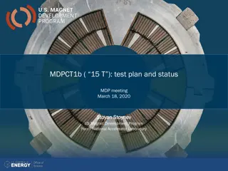
The 13-14 T field level (III) and beyond 15 T FNAL Bi2212 insert SMCT (4-5 T stand alone) in 11T dipole coil and then in SMCT coil 4/28/2020 P. Ferracin -- 20 T hybrid and comparative analysis 45
Action items Define comparison criteria Define CORC specs and Je Continue aperture/thickness/dimension analysis Iron, grading Move progressively from analytical model to simplified FEM of CT, CCT, SMCT, block and CC designs Continue the update of current hybrid program 4/28/2020 P. Ferracin -- 20 T hybrid and comparative analysis 46


")
")


")
")
 and beyond 15 T")