Caterpillar Cat D6N TRACK-TYPE TRACTOR (Prefix GHS) Service Repair Manual Instant Download
Please open the website below to get the complete manualnn//

Download Presentation

Please find below an Image/Link to download the presentation.
The content on the website is provided AS IS for your information and personal use only. It may not be sold, licensed, or shared on other websites without obtaining consent from the author. Download presentation by click this link. If you encounter any issues during the download, it is possible that the publisher has removed the file from their server.
E N D
Presentation Transcript
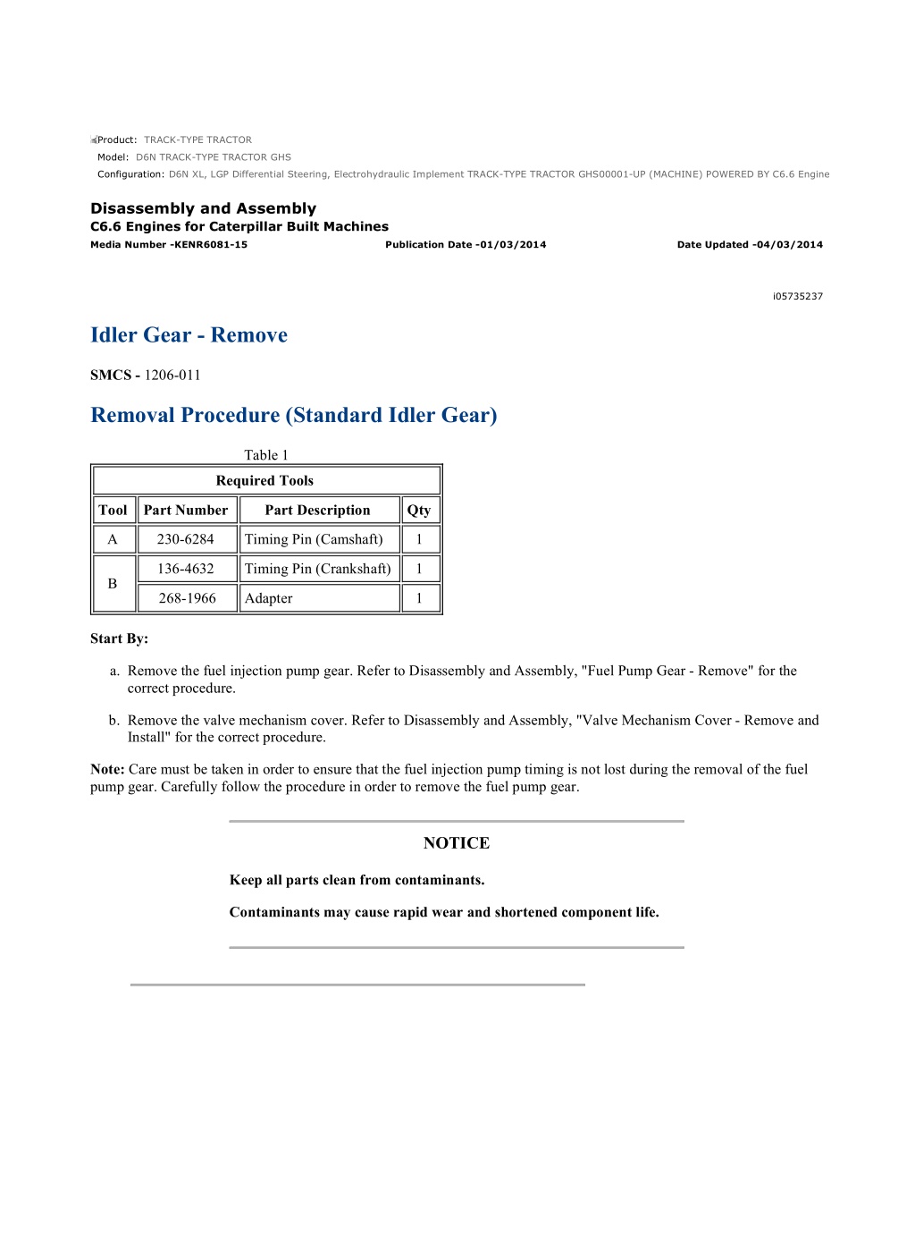
D6N XL, LGP Differential Steering, Electrohydraulic Implement TRACK-TYPE TRA... 1/7 Product: TRACK-TYPE TRACTOR Model: D6N TRACK-TYPE TRACTOR GHS Configuration: D6N XL, LGP Differential Steering, Electrohydraulic Implement TRACK-TYPE TRACTOR GHS00001-UP (MACHINE) POWERED BY C6.6 Engine Disassembly and Assembly C6.6 Engines for Caterpillar Built Machines Media Number -KENR6081-15 Publication Date -01/03/2014 Date Updated -04/03/2014 i05735237 Idler Gear - Remove SMCS - 1206-011 Removal Procedure (Standard Idler Gear) Table 1 Required Tools Tool Part Number Part Description Qty A 230-6284 Timing Pin (Camshaft) 1 136-4632 Timing Pin (Crankshaft) 1 B 268-1966 Adapter 1 Start By: a. Remove the fuel injection pump gear. Refer to Disassembly and Assembly, "Fuel Pump Gear - Remove" for the correct procedure. b. Remove the valve mechanism cover. Refer to Disassembly and Assembly, "Valve Mechanism Cover - Remove and Install" for the correct procedure. Note: Care must be taken in order to ensure that the fuel injection pump timing is not lost during the removal of the fuel pump gear. Carefully follow the procedure in order to remove the fuel pump gear. NOTICE Keep all parts clean from contaminants. Contaminants may cause rapid wear and shortened component life. https://127.0.0.1/sisweb/sisweb/techdoc/techdoc_print_page.jsp?returnurl=/sis... 2021/10/19
D6N XL, LGP Differential Steering, Electrohydraulic Implement TRACK-TYPE TRA... 2/7 Illustration 1 g01337918 Alignment of timing marks 1. Ensure that Tooling (A) is installed into Hole (X) in the camshaft gear. Use Tooling (A) in order to lock the camshaft in the correct position. Note: Ensure that the gears are marked in order to show alignment. Refer to Illustration 1. Illustration 2 g01337919 2. Ensure that Tooling (B) is installed in Hole (Y) in the cylinder block. Use Tooling (B) in order to lock the crankshaft in the correct position. Illustration 3 g01337921 3. Loosen nuts (5) on all rocker arms (6). Unscrew adjusters (4) on all rocker arms (6) until all valves are fully closed. Note: Failure to ensure that ALL adjusters are fully unscrewed can result in contact between the valves and pistons. https://127.0.0.1/sisweb/sisweb/techdoc/techdoc_print_page.jsp?returnurl=/sis... 2021/10/19
D6N XL, LGP Differential Steering, Electrohydraulic Implement TRACK-TYPE TRA... 3/7 4. Mark plate (3) in order to show orientation. Note: Identification will ensure that the plate can be installed in the original orientation. 5. Remove bolts (1). 6. Remove plate (3). Illustration 4 g01337922 7. Remove the assembly of idler gear (2) and hub (7) from the recess in the front housing. Note: The idler gear must be tilted during removal. 8. Remove hub (7) from idler gear (2). Removal Procedure (Early Heavy-Duty Idler Gear) Table 2 Required Tools Tool Part Number Part Description Qty A 230-6284 Timing Pin (Camshaft) 1 136-4632 Timing Pin (Crankshaft) 1 B 268-1966 Adapter 1 Start By: a. Remove the fuel injection pump gear. Refer to Disassembly and Assembly, "Fuel Pump Gear - Remove" for the correct procedure. b. Remove the valve mechanism cover. Refer to Disassembly and Assembly, "Valve Mechanism Cover - Remove and Install" for the correct procedure. Note: Care must be taken in order to ensure that the fuel injection pump timing is not lost during the removal of the fuel pump gear. Carefully follow the procedure in order to remove the fuel pump gear. NOTICE Keep all parts clean from contaminants. Contaminants may cause rapid wear and shortened component life. https://127.0.0.1/sisweb/sisweb/techdoc/techdoc_print_page.jsp?returnurl=/sis... 2021/10/19
https://www.ebooklibonline.com Hello dear friend! Thank you very much for reading. Enter the link into your browser. The full manual is available for immediate download. https://www.ebooklibonline.com
D6N XL, LGP Differential Steering, Electrohydraulic Implement TRACK-TYPE TRA... 4/7 Note: The assembly of heavy-duty idler gear is not serviceable. Do not disassemble the heavy-duty idler gear. Illustration 5 g01337924 Alignment of timing marks 1. Ensure that Tooling (A) is installed into hole (X) in the camshaft gear. Use Tooling (A) in order to lock the camshaft in the correct position. Note: Ensure that the gears are marked in order to show alignment. Refer to Illustration 5. Illustration 6 g01337919 2. Ensure that Tooling (B) is installed in hole (Y) in the cylinder block. Use Tooling (B) in order to lock the crankshaft in the correct position. Illustration 7 g01337921 https://127.0.0.1/sisweb/sisweb/techdoc/techdoc_print_page.jsp?returnurl=/sis... 2021/10/19
D6N XL, LGP Differential Steering, Electrohydraulic Implement TRACK-TYPE TRA... 5/7 3. Loosen nuts (4) on all rocker arms (5). Unscrew adjusters (3) on all rocker arms (5) until all valves are fully closed. Note: Failure to ensure that ALL adjusters are fully unscrewed can result in contact between the valves and pistons. 4. Remove bolts (1) from the assembly of heavy-duty idler gear (2). Illustration 8 g01337922 5. Remove the assembly of idler gear (2) from the recess in the front housing. Note: The idler gear must be tilted during removal. Removal Procedure (Latest Heavy-Duty Idler Gear) Table 3 Required Tools Tool Part Number Part Description Qty A 230-6284 Timing Pin (Camshaft) 1 136-4632 Timing Pin (Crankshaft) 1 B 268-1966 Adapter 1 Bolt (M8 x 80mm) C - 1 Start By: a. If the engine is equipped with an air compressor, remove the air compressor. Refer to Disassembly and Assembly, "Air Compressor - Remove and Install" for the correct procedure. b. If the engine is equipped with an accessory drive, remove the accessory drive. Refer to Disassembly and Assembly, "Accessory Drive - Remove and Install" for the correct procedure. c. Remove the fuel injection pump gear. Refer to Disassembly and Assembly, "Fuel Pump Gear - Remove" for the correct procedure. d. Remove the valve mechanism cover. Refer to Disassembly and Assembly, "Valve Mechanism Cover - Remove and Install" for the correct procedure. Note: Care must be taken in order to ensure that the fuel injection pump timing is not lost during the removal of the fuel pump gear. Carefully follow the procedure in order to remove the fuel pump gear. https://127.0.0.1/sisweb/sisweb/techdoc/techdoc_print_page.jsp?returnurl=/sis... 2021/10/19
D6N XL, LGP Differential Steering, Electrohydraulic Implement TRACK-TYPE TRA... 6/7 NOTICE Keep all parts clean from contaminants. Contaminants may cause rapid wear and shortened component life. Note: The assembly of heavy-duty idler gear is not serviceable. Do not disassemble the heavy-duty idler gear. Illustration 9 g01343977 Alignment of timing marks 1. Ensure that Tooling (A) is installed into Hole (X) in the camshaft gear. Use Tooling (A) in order to lock the camshaft in the correct position. Note: Ensure that the gears are marked in order to show alignment. Refer to Illustration 9. 2. Ensure that Tooling (B) is installed in Hole (Y) in the front housing. Use Tooling (B) in order to lock the crankshaft in the correct position. Illustration 10 g01337921 Typical example 3. Loosen nuts (5) on all rocker arms (6). Unscrew adjusters (4) on all rocker arms (5) until all valves are fully closed. Note: Failure to ensure that ALL adjusters are fully unscrewed can result in contact between the valves and pistons. https://127.0.0.1/sisweb/sisweb/techdoc/techdoc_print_page.jsp?returnurl=/sis... 2021/10/19
D6N XL, LGP Differential Steering, Electrohydraulic Implement TRACK-TYPE TRA... 7/7 4. Remove bolts (1) from the assembly of heavy-duty idler gear (2). Refer to Illustration 9. Illustration 11 g01269933 Typical example 5. Remove the assembly of idler gear (2) from the recess in the front housing. Note: The idler gear must be tilted during removal. Illustration 12 g01348835 Typical example 6. If necessary, remove plate (6). Install Tooling (C) into threaded Hole (Z) in order to remove plate (6). https://127.0.0.1/sisweb/sisweb/techdoc/techdoc_print_page.jsp?returnurl=/sis... 2021/10/19
D6N XL, LGP Differential Steering, Electrohydraulic Implement TRACK-TYPE TRA... 1/10 Product: TRACK-TYPE TRACTOR Model: D6N TRACK-TYPE TRACTOR GHS Configuration: D6N XL, LGP Differential Steering, Electrohydraulic Implement TRACK-TYPE TRACTOR GHS00001-UP (MACHINE) POWERED BY C6.6 Engine Disassembly and Assembly C6.6 Engines for Caterpillar Built Machines Media Number -KENR6081-15 Publication Date -01/03/2014 Date Updated -04/03/2014 i05735238 Idler Gear - Install SMCS - 1206-012 Installation Procedure (Standard Idler Gear) Table 1 Required Tools Tool Part Number Part Description Qty A 230-6284 Timing Pin (Camshaft) 1 136-4632 Timing Pin (Crankshaft) 1 B 268-1966 Adapter 1 NOTICE Keep all parts clean from contaminants. Contaminants may cause rapid wear and shortened component life. 1. Ensure that number one piston is at top dead center on the compression stroke. Refer to System Operation, Testing and Adjusting, "Finding Top Center for No. 1 Piston" for the correct procedure. Illustration 1 g01337918 https://127.0.0.1/sisweb/sisweb/techdoc/techdoc_print_page.jsp?returnurl=/sis... 2021/10/19
D6N XL, LGP Differential Steering, Electrohydraulic Implement TRACK-TYPE TRA... 2/10 Alignment of timing marks 2. Ensure that Tooling (A) is installed into Hole (X) in camshaft gear (1). Illustration 2 g01337947 3. Ensure that Tooling (B) is installed in Hole (Y) in the cylinder block. Use Tooling (B) in order to lock the crankshaft in the correct position. Refer to System Operation, Testing and Adjusting, "Finding Top Center Position for No.1 Piston" for the correct procedure. Illustration 3 g01337949 4. Clean idler gear (2) and inspect the idler gear for wear or damage. Refer to Specifications, "Gear Group (Front)" for more information. If necessary, replace the idler gear. 5. Clean hub (7) and inspect the hub for wear or damage. Refer to Specifications, "Gear Group (Front)" for more information. If necessary, replace the hub. 6. Lubricate hub (7) with clean engine oil. Slide hub (7) into idler gear (2). Ensure that the timing marks are toward the front of the idler gear. https://127.0.0.1/sisweb/sisweb/techdoc/techdoc_print_page.jsp?returnurl=/sis... 2021/10/19
D6N XL, LGP Differential Steering, Electrohydraulic Implement TRACK-TYPE TRA... 3/10 Illustration 4 g01337952 7. Align the timing mark on idler gear (2) with the timing mark on the camshaft gear. Refer to the illustration 1. Install the assembly of idler gear (2) and hub (7) into the recess in the timing case. Ensure that oil Hole (Z) is to the top of the hub. Note: The idler gear must be tilted during installation. Ensure that the holes in the hub are aligned with the holes in the cylinder block. 8. Clean plate (3) and inspect the plate for wear or damage. If necessary, replace the plate. 9. Lubricate plate (3) with clean engine oil. Align the holes in plate (3) with the holes in hub (7). Install the plate in the original orientation. 10. Install bolts (1). 11. Remove Tooling (A) and Tooling (B). Note: Ensure that timing marks are aligned, before removing the Tooling (A) and Tooling (B). 12. Install plug (8) to the cylinder block. Refer to Illustration 2. 13. Tighten bolts (1) to a torque of 44 N m (32 lb ft). https://127.0.0.1/sisweb/sisweb/techdoc/techdoc_print_page.jsp?returnurl=/sis... 2021/10/19
D6N XL, LGP Differential Steering, Electrohydraulic Implement TRACK-TYPE TRA... 4/10 Illustration 5 g01337953 Checking end play by using a set of feeler gauge's 14. Use a set of feeler gauge's in order to check the end play for the idler gear. Refer to Specifications, "Gear Group (Front)" for more information. Illustration 6 g01335426 Checking backlash 15. Check the backlash between the idler gear and the camshaft gear. Refer to Specifications, "Gear Group (Front)" for more information. 16. Check the backlash between the idler gear and the crankshaft gear. Refer to Specifications, "Gear Group (Front)" for more information. 17. Lightly lubricate all of the gears with clean engine oil. End By: a. Install the fuel injection pump gear. Refer to Disassembly and Assembly, "Fuel Pump Gear - Install" for the correct procedure. https://127.0.0.1/sisweb/sisweb/techdoc/techdoc_print_page.jsp?returnurl=/sis... 2021/10/19
D6N XL, LGP Differential Steering, Electrohydraulic Implement TRACK-TYPE TRA... 5/10 Installation Procedure (Early Heavy-Duty Idler Gear) Table 2 Required Tools Tool Part Number Part Description Qty A 230-6284 Timing Pin (Camshaft) 1 136-4632 Timing Pin (Crankshaft) 1 B 268-1966 Adapter 1 9U-7324 Indicator Bracket 1 7H-1942 Dial Indicator 1 C 3S-3268 Indicator Contact Point 1 7H-1940 Universal Attachment 1 NOTICE Keep all parts clean from contaminants. Contaminants may cause rapid wear and shortened component life. 1. Ensure that number one piston is at top dead center on the compression stroke. Refer to System Operation, Testing and Adjusting, "Finding Top Center for No. 1 Piston" for the correct procedure. Illustration 7 g01337924 Alignment of timing marks 2. Ensure that Tooling (A) is installed into Hole (X) in the camshaft gear. https://127.0.0.1/sisweb/sisweb/techdoc/techdoc_print_page.jsp?returnurl=/sis... 2021/10/19
D6N XL, LGP Differential Steering, Electrohydraulic Implement TRACK-TYPE TRA... 6/10 Illustration 8 g01337954 3. Ensure that Tooling (B) is installed in Hole (Y) in the cylinder block. Use Tooling (B) in order to lock the crankshaft in the correct position. Refer to System Operation, Testing and Adjusting, "Finding Top Center Position for No.1 Piston" for the correct procedure. 4. Clean the assembly of idler gear (2) and inspect the assembly of the idler gear for wear or damage. Refer to Specifications , "Gear Group (Front)" for more information. If necessary, replace the assembly of the idler gear. 5. Lubricate the bearings in the assembly of idler gear (2) with clean engine oil. Illustration 9 g01337922 6. Align the timing mark on idler gear (2) with the timing mark on the camshaft gear. Refer to the illustration 7. Install the assembly of idler gear (2) into the recess in the timing case. Ensure that the identification mark TOP is upward. Note: The idler gear must be tilted during installation. Ensure that the holes in assembly of the idler gear are aligned with the holes in the cylinder block. 7. Install bolts (1). 8. Remove Tooling (A) and Tooling (B). Note: Ensure that timing marks are aligned, before removing the Tooling (A) and Tooling (B). 9. Install plug (6) to the cylinder block. Refer to Illustration 8. 10. Tighten bolts (1) to a torque of 44 N m (32 lb ft). https://127.0.0.1/sisweb/sisweb/techdoc/techdoc_print_page.jsp?returnurl=/sis... 2021/10/19
D6N XL, LGP Differential Steering, Electrohydraulic Implement TRACK-TYPE TRA... 7/10 Illustration 10 g01337957 11. Use Tooling (C) in order to check the end play for the heavy-duty idler gear. Refer to Specifications, "Gear Group (Front)" for more information. Illustration 11 g01335426 Checking backlash 12. Check the backlash between the idler gear and the camshaft gear. Refer to Specifications, "Gear Group (Front)" for more information. 13. Check the backlash between the idler gear and the crankshaft gear. Refer to Specifications, "Gear Group (Front)" for more information. 14. Lightly lubricate all of the gears with clean engine oil. End By: a. Install the fuel injection pump gear. Refer to Disassembly and Assembly, "Fuel Pump Gear - Install" for the correct procedure. https://127.0.0.1/sisweb/sisweb/techdoc/techdoc_print_page.jsp?returnurl=/sis... 2021/10/19
D6N XL, LGP Differential Steering, Electrohydraulic Implement TRACK-TYPE TRA... 8/10 Installation Procedure (Latest Heavy-Duty Idler Gear) Table 3 Required Tools Tool Part Number Part Description Qty A 230-6284 Timing Pin (Camshaft) 1 136-4632 Timing Pin (Crankshaft) 1 B 268-1966 Adapter 1 9U-7324 Indicator Bracket 1 7H-1942 Dial Indicator 1 C 3S-3268 Indicator Contact Point 1 7H-1940 Universal Attachment 1 NOTICE Keep all parts clean from contaminants. Contaminants may cause rapid wear and shortened component life. 1. Ensure that number one piston is at the top center Position on the compression stroke. Refer to Systems Operation, Testing and Adjusting, "Finding Top Center Postion for No. 1 Piston" for the correct procedure. Illustration 12 g01343977 Alignment of timing marks 2. Ensure that Tooling (A) is installed into Hole (X) in the camshaft gear. 3. Ensure that Tooling (B) is installed in Hole (Y) in the cylinder block. Use Tooling (B) in order to lock the crankshaft in the correct position. Refer to Systems Operation, Testing and Adjusting, "Finding Top Center Position for No.1 Piston" for the correct procedure. https://127.0.0.1/sisweb/sisweb/techdoc/techdoc_print_page.jsp?returnurl=/sis... 2021/10/19
D6N XL, LGP Differential Steering, Electrohydraulic Implement TRACK-TYPE TRA... 9/10 Illustration 13 g01387344 Typical example 4. Install plate (6) into the recess in the front housing. Note: Ensure that the identification mark TOP is upward. 5. Clean the assembly of idler gear (2) and inspect the assembly of the idler gear for wear or damage. Refer to Specifications, "Gear Group (Front)" for more information. If necessary, replace the assembly of the idler gear. 6. Lubricate the bearings in the assembly of idler gear (2) with clean engine oil. Illustration 14 g01269933 7. Align the timing mark on idler gear (2) with the timing mark on the camshaft gear. Refer to Illustration 12. Install the assembly of idler gear (2) into the recess in the timing case. Ensure that the identification mark TOP is upward. Note: The idler gear must be tilted during installation. Ensure that the holes in the assembly of the idler gear are aligned with the holes in the cylinder block. 8. Install bolts (1). Tighten bolts (1) to a torque of 44 N m (32 lb ft). https://127.0.0.1/sisweb/sisweb/techdoc/techdoc_print_page.jsp?returnurl=/sis... 2021/10/19
D6N XL, LGP Differential Steering, Electrohydraulic Implement TRACK-TYPE T... 10/10 Illustration 15 g01269937 Checking end play by using a dial indicator group 9. Use Tooling (C) in order to check the end play of the idler gear. Refer to Specifications, "Gear Group (Front)" for more information. 10. Use Tooling (C) in order to check the backlash between the idler gear and the camshaft gear. Refer to Specifications, "Gear Group (Front)" for more information. 11. Use Tooling (C) in order to check the backlash between the idler gear and the crankshaft gear. Refer to Specifications, "Gear Group (Front)" for more information. 12. Lightly lubricate all of the gears with clean engine oil. End By: a. Install the fuel injection pump gear. Refer to Disassembly and Assembly, "Fuel Pump Gear - Install" for the correct procedure. b. If the engine is equipped with an air compressor, install the air compressor. Refer to Disassembly and Assembly, "Air Compressor - Remove and Install" for the correct procedure. c. If the engine is equipped with an accessory drive, install the accessory drive. Refer to Disassembly and Assembly, "Accessory Drive - Remove and Install" for the correct procedure. https://127.0.0.1/sisweb/sisweb/techdoc/techdoc_print_page.jsp?returnurl=/sis... 2021/10/19
D6N XL, LGP Differential Steering, Electrohydraulic Implement TRACK-TYPE TRA... 1/3 Product: TRACK-TYPE TRACTOR Model: D6N TRACK-TYPE TRACTOR GHS Configuration: D6N XL, LGP Differential Steering, Electrohydraulic Implement TRACK-TYPE TRACTOR GHS00001-UP (MACHINE) POWERED BY C6.6 Engine Disassembly and Assembly C6.6 Engines for Caterpillar Built Machines Media Number -KENR6081-15 Publication Date -01/03/2014 Date Updated -04/03/2014 i02786790 Housing (Front) - Remove SMCS - 1151-011 Removal Procedure Start By: a. Remove the fan. Refer to Disassembly and Assembly, "Fan - Remove and Install". b. If necessary, remove the alternator. Refer to Disassembly and Assembly, "Alternator - Remove". c. Remove the front pulley. Refer to Disassembly and Assembly, "Vibration Damper and Pulley - Remove". d. Remove the engine oil pan. Refer to Disassembly and Assembly, "Engine Oil Pan - Remove". e. If the engine has an accessory drive, remove the accessory drive. Refer to Disassembly and Assembly, "Accessory Drive - Remove and Install". f. Drain the coolant into a suitable container for storage or disposal. Refer to Operation and Maintenance Manual, "Cooling System Coolant - Drain" for the correct procedure. g. Remove the timing gears. Refer to Disassembly and Assembly, "Gear Group (Front) - Remove and Install". h. Remove the fuel injection pump. Refer to Disassembly and Assembly, "Fuel Injection Pump - Remove". NOTICE Keep all parts clean from contaminants. Contaminants may cause rapid wear and shortened component life. NOTICE Care must be taken to ensure that fluids are contained during performance of inspection, maintenance, testing, adjusting and repair of the product. Be prepared to collect the fluid with suitable containers before opening any compartment or disassembling any component containing fluids. Dispose of all fluids according to local regulations and mandates. https://127.0.0.1/sisweb/sisweb/techdoc/techdoc_print_page.jsp?returnurl=/sis... 2021/10/19
D6N XL, LGP Differential Steering, Electrohydraulic Implement TRACK-TYPE TRA... 2/3 Illustration 1 g01337982 1. Remove bolts (1) that secure bypass tube (2) to front housing (3). Remove bypass tube (2) from the cylinder head. Remove O-rings (4) and (5) from bypass tube (2). Illustration 2 g01337985 2. Remove bolts (7), (8) and (9) from front housing (3). Note: The bolts are three different lengths. Note the positions of the different bolts. 3. Remove front housing (3) from the cylinder block. 4. Remove joint (6). https://127.0.0.1/sisweb/sisweb/techdoc/techdoc_print_page.jsp?returnurl=/sis... 2021/10/19
D6N XL, LGP Differential Steering, Electrohydraulic Implement TRACK-TYPE TRA... 3/3 Illustration 3 g01337987 5. Remove thrust washer (10) from the cylinder block. https://127.0.0.1/sisweb/sisweb/techdoc/techdoc_print_page.jsp?returnurl=/sis... 2021/10/19
D6N XL, LGP Differential Steering, Electrohydraulic Implement TRACK-TYPE TRA... 1/5 Product: TRACK-TYPE TRACTOR Model: D6N TRACK-TYPE TRACTOR GHS Configuration: D6N XL, LGP Differential Steering, Electrohydraulic Implement TRACK-TYPE TRACTOR GHS00001-UP (MACHINE) POWERED BY C6.6 Engine Disassembly and Assembly C6.6 Engines for Caterpillar Built Machines Media Number -KENR6081-15 Publication Date -01/03/2014 Date Updated -04/03/2014 i02980900 Housing (Front) - Install SMCS - 1151-012 Installation Procedure Table 1 Required Tools Tool Part Number Part Description Qty A 6V-6640 Sealant 1 Guide Bolt (M8 by 80 mm) B - 2 319-6486 Alignment Tool 1 C Bolts (M10 by 50 mm) - 3 D - Straight Edge 1 E 1U-6396 O-Ring Assembly Compound 1 NOTICE Keep all parts clean from contaminants. Contaminants may cause rapid wear and shortened component life. 1. Ensure that the front housing is clean and free from damage. If necessary, replace the front housing. Install blanking plugs to a new front housing. Use Tooling (A) to seal all D-plugs. 2. Check the condition of the crankshaft front seal. If the front seal is damaged, remove the front seal from the front housing. 3. Clean all the mating surfaces of the cylinder block. https://127.0.0.1/sisweb/sisweb/techdoc/techdoc_print_page.jsp?returnurl=/sis... 2021/10/19
D6N XL, LGP Differential Steering, Electrohydraulic Implement TRACK-TYPE TRA... 2/5 Illustration 1 g01337987 4. Install thrust washer (10) into the recess in the cylinder block. Refer to Disassembly and Assembly, "Camshaft - Install" for more information. Illustration 2 g01338000 5. Install Tooling (B) to the cylinder block. Refer to Illustration 2. 6. Align a new joint (6) with Tooling (B) . Install the joint to the cylinder block. Note: Ensure that two circular tabs (X) on the joint are engaged in two holes (Y) in the cylinder block. https://127.0.0.1/sisweb/sisweb/techdoc/techdoc_print_page.jsp?returnurl=/sis... 2021/10/19
D6N XL, LGP Differential Steering, Electrohydraulic Implement TRACK-TYPE TRA... 3/5 Illustration 3 g01338001 Typical example 7. Install Tooling (C) to the cylinder block. 8. Install the front housing over Tooling (B) and Tooling (C) onto the cylinder block. Illustration 4 g01338002 (7) M8 by 20 mm (8) M8 by 35 mm (9) M8 by 25 mm 9. Install bolts (9) to front housing (3) finger tight. 10. Remove Tooling (B) . https://127.0.0.1/sisweb/sisweb/techdoc/techdoc_print_page.jsp?returnurl=/sis... 2021/10/19
D6N XL, LGP Differential Steering, Electrohydraulic Implement TRACK-TYPE TRA... 4/5 11. Loosely install bolts (7) and (8) . Refer to Illustration 4 for the correct position of the bolts. 12. Align the bottom face of front housing (3) to the lower machined face of the cylinder block. Use a Tooling (D) and a feeler gauge in order to check the alignment between the front housing and the cylinder block. Refer to Illustration 3. Refer to Specifications, "Front Housing and Covers" for further information. Illustration 5 g01338003 13. Tighten bolts (7) , (8) and (9) in the sequence that is shown in illustration 5 to a torque of 28 N m (20 lb ft). Note: Ensure that the housing and the cylinder block are correctly aligned. 14. Remove Tooling (C) from the cylinder block. 15. If necessary, install a new crankshaft front seal. Refer to Disassembly and Assembly, "Crankshaft Front Seal - Remove and Install". https://127.0.0.1/sisweb/sisweb/techdoc/techdoc_print_page.jsp?returnurl=/sis... 2021/10/19
D6N XL, LGP Differential Steering, Electrohydraulic Implement TRACK-TYPE TRA... 5/5 Illustration 6 g01337982 Typical example 16. Install new O-ring seals (4) and (5) to bypass tube (1) . Use Tooling (E) in order to lubricate the O-ring seals. Install bypass tube (2) to the cylinder head. Install bolts (1) . Tighten the bolts to a torque of 22 N m (16 lb ft). End By: a. Install the fuel injection pump. Refer to Disassembly and Assembly, "Fuel Injection Pump - Install". b. Install the timing gears. Refer to Disassembly and Assembly, "Gear Group (Front) - Install". c. If the engine has an accessory drive, install the accessory drive. Refer to Disassembly and Assembly, "Accessory Drive - Remove and Install". d. Install the engine oil pan. Refer to Disassembly and Assembly, "Engine Oil Pan - Install". e. Install the front pulley. Refer to Disassembly and Assembly, "Vibration Damper and Pulley - Install". f. If necessary, install the alternator. Refer to Disassembly and Assembly, "Alternator - Install". g. Install the fan. Refer to Disassembly and Assembly, "Fan - Remove and Install". h. Fill the cooling system with coolant. Refer to Operation and Maintenance Manual, "Cooling System Coolant - Fill" for the correct procedure. https://127.0.0.1/sisweb/sisweb/techdoc/techdoc_print_page.jsp?returnurl=/sis... 2021/10/19
D6N XL, LGP Differential Steering, Electrohydraulic Implement TRACK-TYPE TRA... 1/4 Product: TRACK-TYPE TRACTOR Model: D6N TRACK-TYPE TRACTOR GHS Configuration: D6N XL, LGP Differential Steering, Electrohydraulic Implement TRACK-TYPE TRACTOR GHS00001-UP (MACHINE) POWERED BY C6.6 Engine Disassembly and Assembly C6.6 Engines for Caterpillar Built Machines Media Number -KENR6081-15 Publication Date -01/03/2014 Date Updated -04/03/2014 i02786793 Accessory Drive - Remove and Install SMCS - 1207-010 Removal Procedure Table 1 Required Tools Tool Part Number Part Description Qty 8H-0663 Bearing Puller 1 5F-7345 Puller 1 A 126-7183 Crossblock 1 126-7177 Puller Leg 2 NOTICE Keep all parts clean from contaminants. Contaminants may cause rapid wear and shortened component life. NOTICE Care must be taken to ensure that fluids are contained during performance of inspection, maintenance, testing, adjusting and repair of the product. Be prepared to collect the fluid with suitable containers before opening any compartment or disassembling any component containing fluids. Dispose of all fluids according to local regulations and mandates. https://127.0.0.1/sisweb/sisweb/techdoc/techdoc_print_page.jsp?returnurl=/sis... 2021/10/19
D6N XL, LGP Differential Steering, Electrohydraulic Implement TRACK-TYPE TRA... 2/4 Illustration 1 g01269954 Typical example 1. Remove allen head screw (1) from accessory drive housing (8). Remove allen head screws (6) from accessory drive housing (8). 2. Remove accessory drive housing (8) from the front housing. 3. If necessary, follow Steps 3.a through 3.c in order to disassemble the accessory drive. a. Remove circlip (2) from accessory drive housing (8). b. Place accessory drive housing (8) onto a suitable support. Press the assembly of gear (4) and bearings (3) and (5) out of accessory drive housing (8). Use Tooling (A) in order to remove bearings (3) and (5) from gear (4). c. Remove O-ring seal (7) from accessory drive housing (8). Installation Procedure Table 2 Required Tools Tool Part Number Part Description Qty B 7M-7456 Bearing Mount Compound - C 207-1601 Rubber Lubricant 1 D 9S-3263 Thread Lock Compound 1 NOTICE Keep all parts clean from contaminants. Contaminants may cause rapid wear and shortened component life. https://127.0.0.1/sisweb/sisweb/techdoc/techdoc_print_page.jsp?returnurl=/sis... 2021/10/19
Suggest: If the above button click is invalid. Please download this document first, and then click the above link to download the complete manual. Thank you so much for reading
D6N XL, LGP Differential Steering, Electrohydraulic Implement TRACK-TYPE TRA... 3/4 Illustration 2 g01264852 Typical example 1. If necessary, follow Steps 1.a through 1.e in order to assemble the accessory drive. a. Inspect the condition of the teeth and the splines of gear (4) for wear or damage. Inspect bearings (3) and (5), circlip (2), and the front housing for wear or damage. Replace any components that are worn or damaged. b. Apply a small continuous bead of Tooling (B) to inner surface (X) of bearing (5). Place the gear shaft on a suitable support. Press on the inner race of bearing (5) until the bearing (5) is against the shoulder of gear (4). Remove any excess sealant. c. Apply a small continuous bead of Tooling (B) to inner surface (Z) of bearing (3). Place the inner race of bearing (3) onto a suitable support. Press the shaft of gear (4) into bearing (3) until the shoulder of the gear is against the bearing. Remove any excess sealant. d. Apply a small continuous bead of Tooling (B) to the outer surface (Y) of bearings (3) and (5). Place accessory drive housing (8) on a suitable support. Press the assembly of the gear into the accessory drive housing. Ensure that bearing (5) is against the front face of the recess in accessory drive housing (8). Remove any excess sealant. e. Install circlip (2) into the groove in accessory drive housing (8). Ensure that circlip (2) is correctly positioned in the groove. 2. Lightly lubricate a new O-ring seal (7) with Tooling (C). Install the O-ring seal into the groove in accessory drive housing (8). 3. Inspect the bore in the front housing for damage. If necessary, replace the front housing. Refer to Disassembly and Assembly, "Housing (Front) - Remove" and Disassembly and Assembly, "Housing (Front) - Install". 4. Lightly lubricate bearing (3), bearing (5), and gear (4) with clean engine lubricating oil. Install the assembly of the accessory drive to the front housing. Ensure that the flange on the accessory drive housing is flush with the front housing. 5. Apply Tooling (D) to allen head screws (1) and (6). Install allen head screws (1) and (6) to accessory drive housing (8). 6. Tighten the allen head screws to a torque of 22 N m (16 lb ft). https://127.0.0.1/sisweb/sisweb/techdoc/techdoc_print_page.jsp?returnurl=/sis... 2021/10/19
https://www.ebooklibonline.com Hello dear friend! Thank you very much for reading. Enter the link into your browser. The full manual is available for immediate download. https://www.ebooklibonline.com