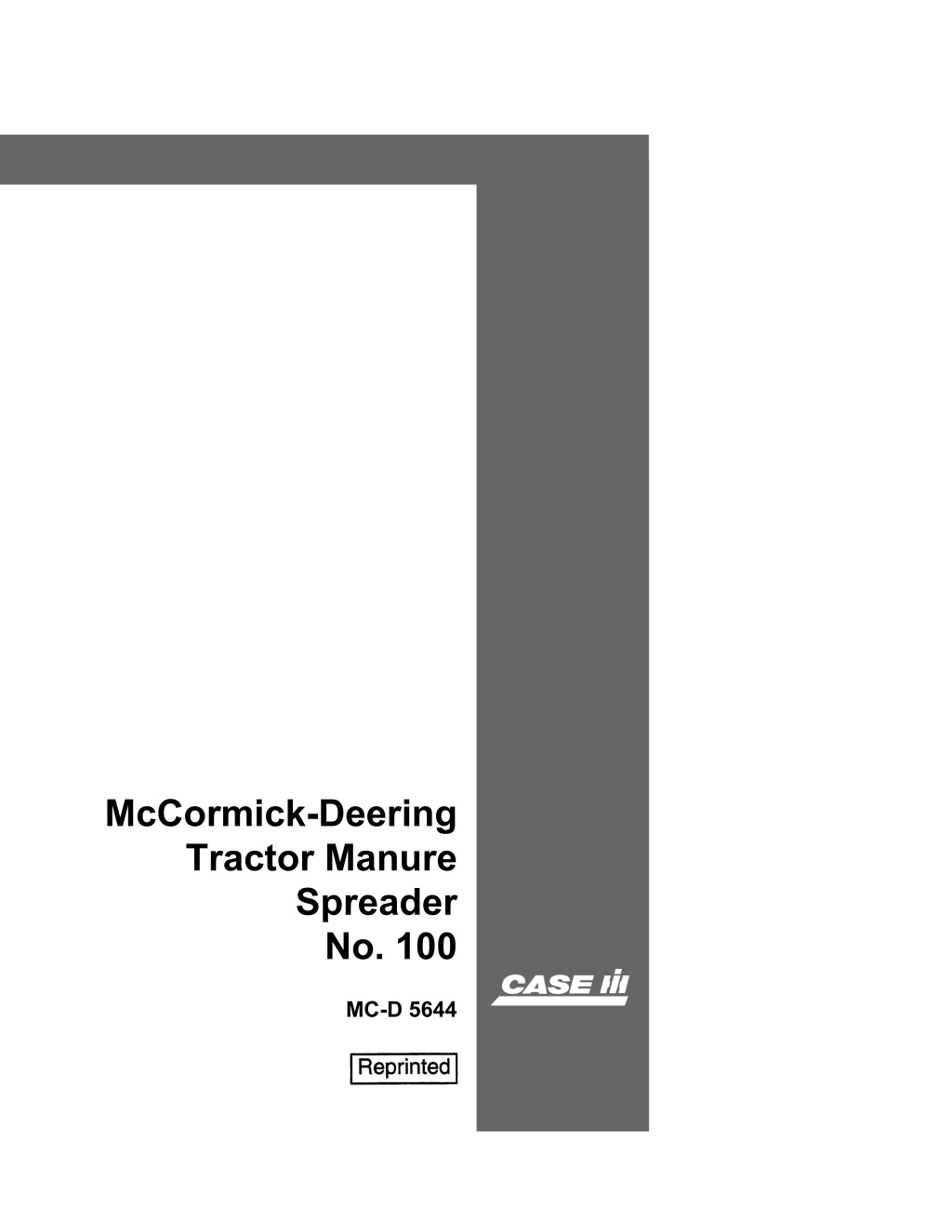
Case IH McCormick-Deering Tractor Manure Spreader No. 100 Operator’s Manual Instant Download (Publication No.MC-D 5644)
Please open the website below to get the complete manualnn//
Download Presentation

Please find below an Image/Link to download the presentation.
The content on the website is provided AS IS for your information and personal use only. It may not be sold, licensed, or shared on other websites without obtaining consent from the author. Download presentation by click this link. If you encounter any issues during the download, it is possible that the publisher has removed the file from their server.
E N D
Presentation Transcript
McCormick-Deering Tractor Manure Spreader No. 100 MC-D 5644
6 THIS SAFETY ALERT SYMBOL INDICATES IMPORTANT SAFETY MESSAGES IN THIS MANUAL. WHEN YOU SEE THIS SYMBOL, , CAREFULL Y READ THE MESSAGE THAT FOLLOWS AND BE ALERT TO THE POSSIBILITY OF PERSONAL INJURY OR DEA TH. M171B If Safety Decals on this machine use the words Danger, Warning or Caution, which are defined as follows: DANGER: Indicates an immediate hazardous situation which if not avoided, will result in death or serious injury. The color associated with Danger is RED. WARNING: Indicates an potentially hazardous situation which if not avoided, will result in serious injury. The color associated with Warning is ORANGE. CAUTION: Indicates an potentially hazardous situation which if not avoided, may result in minor or moderate injury. It may also be used to alert against unsafe practices. The color associated with Caution is YELLOW. If Safety Decals on this machine are ISO two panel Pictorial, decals are defined as follows: The first panel indicates the nature of the hazard. The second panel indicates the appropriate avoidance of the hazard. Background color is YELLOW.IC'\ 6 WARNING IMPROPER OPERATION OF THIS MACHINE CAN CAUSE INJURY OR DEATH. BEFORE USING THIS MACHINE, MAKE CERTAIN THAT EVERY OPERATOR: Prohibition symbols such as \y X and 8 if used, are RED. Is instructed in safe and proper use of the machine. Reads and understands the Manual(s) pertaining to the machine. Reads and understands ALL Safety Decals on the machine. Clears the area of other persons. Learns and practices safe use of machine controls in a safe, clear area before operating this machine on a job site. It is your responsibility to observe pertinent laws and regulations and follow Case Corporation instructions on machine operation and maintenance. Bur 0-00000 2001 Case Corporation March, 1995 (Revised October, 1997) CASE and IH are registered trade marks of Case Corporation
Instruction Manual and Parts List Setting Up and Operating McCormick-Deering Tractor Manure Spreader ~ " No. 100 This manual contains instructions for setting up and operating and, in addition, a parts list trations of the various units arranged so that parts wanted may readily be located. detailed mus- INTERNATIONAL HARVESTER COMPANY 180 NORTH MrcHWiAN AVE. CHICAGO, ILLINOiS. U.S.A.
https://www.ebooklibonline.com Hello dear friend! Thank you very much for reading. Enter the link into your browser. The full manual is available for immediate download. https://www.ebooklibonline.com
7. INSTRUCTIONS fOR SETTING UP (Operaling I rlalmellons are on page 17) Remove wires and arran!;;,; PUtt ; 1 . ilYI,-"/,, all bearings and ma ,ng kerosene 10 cut lhc paim on and see that they work if necessary. Bolts must be used in the hol,)s are unless nth Nlse shown. or in parts to which which are Shaded portions in the illustrations shew paris to be assembled: these musl be placed on the machine in the order numbered. it should be understood and and to mean from a the \Ve reserve on any machine 'U',M"'''''''' J than J miles per hour if .',, Pfl,dpt with steel wheels, Do nol dr/te is
must. 1 1. Place bottom on wooden borses about 191' higb and remove filler boards. right amI left. 2. Attach sides and side angle gussets to bottom with bolts. machine 3. Attach angles to' sides and gussets, using "Au and x carriage bolts at "B", placing angle with stud on left rear side. x machine bolts at
4 must. z ; musL 2A
See /llusli- 2 and 2A bolts x \vith supports, right and 1. Attach at "A", Leave bolts 2. Attach front end gate to side sheet supports with at "S" and x x boits at "C", Leave bolts loose, machine 3. bolts 4. bolts at. HDttt- xl X x I 5. Attach sectors machine bolts at bolts loose, Remove control md hom leveL G. 7. Insert outer end of lever nf';fI rtTH), over cotteL Place outer half or machine hole in side inner half of and insert inner end of lever md and feed rod to levers and secure with 8. Attach chain cotteL See lllu:st 2A also, x 1 y
must. 3 Attach axle brackets, right and left, with axle and rear apron shaft in place, to bottom. angles with % x %ff m.achine bolts. L x %" carriage bolts at "A". 2. Attach arch to sides with J. Replace filler boards. right and left. 4. Attach chain raising yoke brace bracket with % x I" carriage bolt.
Suggest: If the above button click is invalid. Please download this document first, and then click the above link to download the complete manual. Thank you so much for reading
7 must. 4 1. Attach adjusting feed rod, swivel and spring to feed roller arm. Insert (7)40 lubricating fitting into under side or swivel. 2. Attach pawl bracket assembly to arch with x lit carriage bolts. with %i x 3. Attach upper at "A" and right and carriage bolts x J1l "'" ...... ",'" 4. Attach feed cam arm return spring and dip to arch with machine bolt. Adjust spring tension. 11:
https://www.ebooklibonline.com Hello dear friend! Thank you very much for reading. Enter the link into your browser. The full manual is available for immediate download. https://www.ebooklibonline.com

