Bobcat S100 Skid Steer Loader Service Repair Manual Instant Download (SN A2G811001 and Above, SN A8ET11001 - A8ET19999)
Please open the website below to get the complete manualnn// n

Download Presentation

Please find below an Image/Link to download the presentation.
The content on the website is provided AS IS for your information and personal use only. It may not be sold, licensed, or shared on other websites without obtaining consent from the author. Download presentation by click this link. If you encounter any issues during the download, it is possible that the publisher has removed the file from their server.
E N D
Presentation Transcript
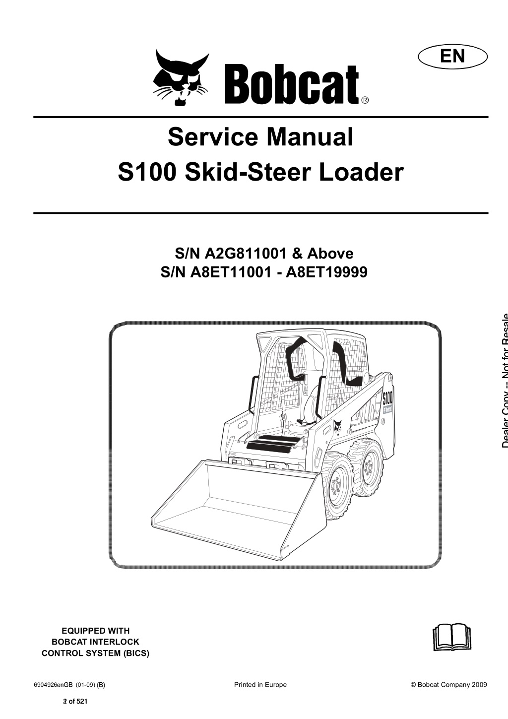
EN Service Manual S100 Skid-Steer Loader S/N A2G811001 & Above S/N A8ET11001 - A8ET19999 Dealer Copy -- Not for Resale EQUIPPED WITH BOBCAT INTERLOCK CONTROL SYSTEM (BICS) Printed in Europe Bobcat Company 2009 6904926 (01-09) 2 of 521
MAINTENANCE SAFETY Instructions are necessary before operating or servicing machine. Read and understand the Operation & Maintenance Manual, Operator s Handbook and signs (decals) on machine. Follow warnings and instructions in the manuals when making repairs, adjustments or servicing. Check for correct function after adjustments, repairs or service. Untrained operators and failure to follow instructions can cause injury or death. WARNING W-2003-0903 Safety Alert Symbol: This symbol with a warning statement, means: Warning, be alert! Your safety is involved! Carefully read the message that follows. CORRECT CORRECT CORRECT B-10731a B-15590 B-15591 Cleaning and maintenance are required daily. Never service the Bobcat Skid- Steer Loader without instructions. Use the correct procedure to lift or lower operator cab. WRONG WRONG WRONG Dealer Copy -- Not for Resale B-15592 B-15593 B-15599 Have good ventilation when welding or grinding painted parts. Wear dust mask when grinding painted parts. Toxic dust and gas can be produced. Avoid exhaust fume leaks which can kill without warning. Exhaust system must be tightly sealed. Disconnecting or loosening any hydraulic tubeline, hose, fitting, component or a part failure can cause lift arms to drop. Do not go under lift arms when raised unless supported approved lift arm support device. Replace it if damaged. Never work on loader with lift arms up unless lift arms are held by an approved lift arm support device. Replace if damaged. Never modify equipment or add attachments not approved by Bobcat Company. by an WRONG WRONG WRONG B-15601 B-6589 B-15600 Stop, cool and clean engine of flammable materials checking fluids. Never service or adjust loader with the engine running unless instructed to do so in the manual. Avoid contact hydraulic fluid or diesel fuel under pressure. It can penetrate the skin or eyes. Never fill fuel tank with engine running, while smoking or when near open flame. Keep body, jewelry and clothing away from moving electrical contact, hot parts and exhaust. Wear eye protection to guard from battery acid, compressed springs, fluids under pressure and flying debris when engines are running or tools are used. Use eye protection approved for type of welding. Keep rear door closed except for service. Close and latch door before operating the loader. Lead-acid flammable and explosive gases. Keep arcs, sparks, flames and lighted tobacco batteries. Batteries contain acid which burns eyes or skin on contact. Wear protective clothing. If acid contacts body, flush well with water. For eye contact flush well and get immediate attention. batteries produce before parts, away from with leaking medical Maintenance procedures which are given in the Operation & Maintenance Manual can be performed by the owner / operator without any specific technical training. Maintenance procedures which are not in the Operation & Maintenance Manual must be performed ONLY BY QUALIFIED BOBCAT SERVICE PERSONNEL. Always use genuine Bobcat replacement parts. The Service Safety Training Course is available from your Bobcat dealer. MSW08-0805 3 of 521
ALPHABETICAL INDEX AIR CLEANER........................................................70-01 AIR CLEANER SERVICE........................................10-01 ALTERNATOR.........................................................60-01 HYDRAULIC / HYDROSTATIC SYSTEM................ 10-01 HYDRAULIC PUMP ................................................ 20-01 HYDRAULIC SYSTEM INFORMATION..................20-01 HYDROSTATIC MOTOR ......................................... 30-01 HYDROSTATIC PUMP............................................ 30-01 HYDROSTATIC SYSTEM INFORMATION..............30-01 BACK-UP ALARM SYSTEM........................10-01, 60-01 BATTERY..................................................................60-01 BLOWER FAN......................................................... 20-01 BOBCAT CONTROLLER (MAIN)............................60-01 BOBCAT INTERLOCK CONTROL SYSTEM (BICS)......................................................60-01 BOB-TACH (HAND LEVER).........................10-01, 50-01 BOB-TACH (POWER) BLOCK................................ 20-01 BOB-TACH (POWER-OPTION).....................10-01, 50-01 BRAKE.................................................................... 40-01 BUCKET POSITION VALVE.................................... 20-01 INSTRUMENT PANELS ......................................... 60-01 LIFT ARM BYPASS CONTROL VALVE .................. 20-01 LIFT ARMS...............................................................50-01 LIFT ARM SUPPORT DEVICE ............................... 10-01 LIFTING AND BLOCKING THE LOADER ..............10-01 LIGHTS ................................................................... 60-01 LOADER SPECIFICATIONS............................. SPEC-01 LOADER STORAGE AND RETURN TO SERVICE.10-01 LUBRICATING THE LOADER.................................10-01 LUBRICATION SYSTEM......................................... 70-01 CAB DOOR............................................................. 50-01 CAMSHAFT AND TIMING GEARS..........................70-01 CASE DRAIN FILTER............................................. 30-01 CHAINCASE ........................................................... 40-01 CHARGE PRESSURE ........................................... 30-01 CONTROL HANDLE / LEVER ................................ 50-01 CONTROL PANEL ..................................................50-01 CONTROL PANEL SETUP .....................................60-01 CONTROL PEDALS AND LINKAGE....................... 50-01 CONVERSIONS.................................................SPEC-01 CRANKSHAFT AND PISTONS............................... 70-01 CYLINDER (BOB-TACH)......................................... 20-01 CYLINDER HEAD................................................... 70-01 CYLINDER (LIFT)................................................... 20-01 CYLINDER (TILT).................................................... 20-01 MAINTENANCE CLOCK......................................... 60-01 MAIN RELIEF VALVE...............................................20-01 MUFFLER ............................................................... 70-01 OIL COOLER .......................................................... 20-01 OPERATOR CAB .........................................10-01, 50-01 OPERATOR SEAT................................................... 50-01 OPERATOR SEAT (SUSPENSION)........................50-01 Dealer Copy -- Not for Resale PASSWORD SETUP............................................... 60-01 PIVOT PINS..............................................................10-01 REAR DOOR ..........................................................50-01 REAR GRILL ..........................................................50-01 REGULAR MAINTENANCE....................................80-01 REMOTE START TOOL.......................................... 10-01 DIAGNOSTICS SERVICE CODES......................... 60-01 DRIVE BELT............................................................ 30-01 DRIVE COMPONENETS........................................ 40-01 ELECTRICAL SYSTEM INFORMATION ................ 60-01 ENGINE COOLING SYSTEM......................10-01, 70-01 ENGINE INFORMATION......................................... 70-01 ENGINE LUBRICATION SYSTEM ...........................10-01 ENGINE SPEED CONTROL...................................70-01 SEAT BAR............................................................... 50-01 SEAT BAR SENSOR............................................... 60-01 SERVICE PC (LAPTOP COMPUTER)....................60-01 SERVICE SCHEDULE.............................................10-01 SPARK ARRESTOR MUFFLER..............................10-01 STARTER................................................................ 60-01 STOPPING THE ENGINE AND LEAVING THE LOADER......................................... 10-01 FINAL DRIVE TRANSMISSION (CHAINCASE) .....10-01 FLYWHEEL AND HOUSING...................................70-01 FLYWHEEL RPM SENSOR......................................60-01 FRONT AUXILIARY HYDRAULIC COUPLER BLOCK......................................................................20-01 FUEL SYSTEM..............................................10-01, 70-01 FUEL TANK...............................................................50-01 TIRE MAINTENANCE............................................. 10-01 TORQUE SPECIFICATIONS FOR BOLTS........ SPEC-01 TOWING THE LOADER.......................................... 10-01 TRACTION LOCK ................................................... 60-01 TRANSPORTING THE BOBCAT LOADER............. 10-01 TROUBLESHOOTING ............................................ 80-01 HEATER COIL......................................................... 80-01 HEATER FAN.......................................................... 80-01 HEATER SYSTEM .................................................. 80-01 HEATER UNIT......................................................... 80-01 HEATER VALVE...................................................... 80-01 HYDRAULIC CONNECTION SPECS ................SPEC-01 HYDRAULIC CONTROL VALVE..............................20-01 HYDRAULIC FLUID RESERVOIR .......................... 20-01 HYDRAULIC / HYDROSTATIC FILTERS..................20-01 HYDRAULIC / HYDROSTATIC FLUID SPECIFICATIONS ..................................SPEC-01 WINDOW (FRONT DOOR)..................................... 50-01 WINDOW (REAR) ................................................... 50-01 WINDOW (SIDE).....................................................50-01 WINDOW (TOP)...................................................... 50-01 5 of 521
https://www.ebooklibonline.com Hello dear friend! Thank you very much for reading. Enter the link into your browser. The full manual is available for immediate download. https://www.ebooklibonline.com
CONTENTS SAFETY & MAINTENANCE FOREWORD . . . . . . . . . . . . . . . . . . . . . . . . . . . . . . . . . . . . . . . . . . .II SAFETY INSTRUCTIONS . . . . . . . . . . . . . . . . . . . . . . . . . . . . . . . . .V HYDRAULIC SYSTEM FIRE PREVENTION. . . . . . . . . . . . . . . . . . . . . . . . . . . . . . . . . . . . .VII SERIAL NUMBER LOCATIONS. . . . . . . . . . . . . . . . . . . . . . . . . . . . IX HYDROSTATIC SYSTEM DELIVERY REPORT . . . . . . . . . . . . . . . . . . . . . . . . . . . . . . . . . . . . .X LOADER IDENTIFICATION . . . . . . . . . . . . . . . . . . . . . . . . . . . . . . . XI DRIVE SYSTEM SAFETY AND MAINTENANCE . . . . . . . . . . . . . . . . . . . . . . . . . 10-01 HYDRAULIC SYSTEM . . . . . . . . . . . . . . . . . . . . . . . . . . . . . . . . 20-01 MAIN FRAME HYDROSTATIC SYSTEM. . . . . . . . . . . . . . . . . . . . . . . . . . . . . . 30-01 DRIVE SYSTEM. . . . . . . . . . . . . . . . . . . . . . . . . . . . . . . . . . . . . 40-01 ELECTRICAL SYSTEM & ANALYSIS MAIN FRAME. . . . . . . . . . . . . . . . . . . . . . . . . . . . . . . . . . . . . . . 50-01 ELECTRICAL SYSTEM & ANALYSIS . . . . . . . . . . . . . . . . . . . . 60-01 Dealer Copy -- Not for Resale ENGINE ENGINE SERVICE . . . . . . . . . . . . . . . . . . . . . . . . . . . . . . . . . . . 70-01 SERVICE HEATER . . . . . . . . . . . . . . . . . . . . . . . . . . . . . . . . . . . . . . . . . . . 80-01 SPECIFICATIONS . . . . . . . . . . . . . . . . . . . . . . . . . . . . . . . . SPEC-01 HEATER SPECIFICATIONS SPECIFICATION I S100 Service Manual 7 of 521
FOREWORD This manual is for the Bobcat loader mechanic. It provides necessary servicing and adjustment procedures for the Bobcat loader and its component parts and systems. Refer to the Operation & Maintenance Manual for operating instructions, starting procedure, daily checks, etc. A general inspection of the following items must be made after the loader has had service or repair: 1. Check that the ROPS/FOPS (Including side screens) is in good condition and is not modified. 9. The parking brake must function correctly. 2. Check that ROPS mounting hardware is tightened and is Bobcat approved. 10. Enclosure door latches must open and close freely. 3. The seat belt must be correctly installed, functional and in good condition. 11. Bob-Tach linkages correctly and be in good condition. wedges must and function 4. The correctly adjusted, clean and lubricated. seat bar must be 12. Safety treads must be in good condition. Dealer Copy -- Not for Resale 5. Check lift arm support device, replace if damaged. 13. Check for correct function of indicator lamps. 6. Machine signs (decals) must be legible and in the correct location. 14. Check hydraulic fluid level, engine oil level and fuel supply. 7. Steering levers, hand controls and foot pedals must return to neutral (as applicable). 15. Inspect hydraulic fluid leaks. for fuel, oil or 8. Check for correct function of the work lights. 16. Lubricate the loader. FW SSL-0308 SM II S100 Service Manual 8 of 521
17. Check the condition of the battery and cables. 22. Check modification not completed. for any field 18. Inspect the air cleaner for damage or leaks. Check the condition of the element. 23. Operate the machine and check all functions. 19. Check the electrical charging system. 24. Check for correct function of the Bobcat Interlock Control System (BICS ) before the machine is returned to the customer. 25. Check function or condition of all equipped options and accessories (examples: back- up alarm, fire extinguisher, rotating beacon, lift kits, etc.). 26. Recommend to the owner that all necessary corrections be made before the machine is returned to service. 20. Check tires for wear and pressure. Check tracks for wear and tension. Use only approved tires or tracks. 21. Inspect for loose or broken parts or connections. Dealer Copy -- Not for Resale FW SSL-0308 SM III S100 Service Manual 9 of 521
The following publications provide information on the safe use and maintenance of the Bobcat machine and attachments: SAFETY INSTRUCTIONS Safety Alert Symbol The Delivery Report is used to assure that complete instructions have been given to the new owner and that the machine is in safe operating condition. This symbol with a warning statement means: Warning, be alert! Your safety is involved! Carefully read the message that follows. The Operation & Maintenance Manual delivered with the machine or attachment contains operating information as well as routine maintenance and service procedures. It is a part of the machine and can be stored in a container provided on the machine. Replacement Operation & Maintenance Manuals can be ordered from your Bobcat dealer. WARNING Instructions are necessary before operating or servicing machine. Read and understand the Operation & Maintenance Handbook and signs (decals) on machine. Follow warnings and instructions in the manuals when making repairs, adjustments or servicing. Check for correct function after adjustments, repairs or service. Untrained operators and failure to follow instructions can cause injury or death. Machine signs (decals) instruct on the safe operation and care of your Bobcat machine or attachment. The signs and their locations are shown in the Operation & Maintenance Manual. Replacement available from your Bobcat dealer. Manual, Operator s signs are An Operator s Handbook fastened to the operator cab. It s brief instructions are convenient to the operator. The handbook is available from your dealer in an English edition or one of many other languages. See your Bobcat dealer for more information on translated versions. W-2003-0903 IMPORTANT Dealer Copy -- Not for Resale The AEM Safety Manual delivered with the machine gives general safety information. This notice identifies procedures which must be followed to avoid damage to the machine. The Service Manual and Parts Manual are available from your dealer for use by mechanics to do shop-type service and repair work. I-2019-0284 The Skid-Steer Loader Operator Training Course is available through your www.training.bobcat.com or www.bobcat.com. This course is intended to provide rules and practices of correct operation of the Skid-Steer Loader. The course is available in English and Spanish versions. DANGER local dealer or at The signal word DANGER on the machine and in the manuals indicates a hazardous situation which, if not avoided, will result in death or serious injury. Service Safety Training Courses are available from your Bobcat dealer or at www.training.bobcat.com or www.bobcat.com. They provide information for safe and correct service procedures. D-1002-1107 WARNING The Skid-Steer Loader Safety Video is available from your Bobcat dealer or at www.training.bobcat.com or www.bobcat.com. The signal word WARNING on the machine and in the manuals indicates a potentially hazardous situation which, if not avoided, could result in death or serious injury. W-2044-1107 SI SSL-0308 SM V S100 Service Manual 11 of 521
SAFETY INSTRUCTIONS (CONTD) The dealer and owner / operator review the recommended uses of the product when delivered. If the owner / operator will be using the machine for a different application(s) he or she must ask the dealer for recommendations on the new use. Cutting or drilling concrete containing sand or rock containing quartz may result in exposure to silica dust. Do not exceed Permissible Exposure Limits (PEL) to silica dust as determined by OSHA or other job site Rules and Regulations. Use a respirator, water spray or other means to control dust. Silica dust can cause lung disease and is known to the state of California to cause cancer. Dealer Copy -- Not for Resale SI SSL-0308 SM VI S100 Service Manual 12 of 521
FIRE PREVENTION Hydraulic System Check hydraulic tubes, hoses and fittings for damage and leakage. Never use open flame or bare skin to check for leaks. Hydraulic tubes and hoses must be properly routed and have adequate support and secure clamps. Tighten or replace any parts that show leakage. Maintenance Always clean fluid spills. Do not use gasoline or diesel fuel for cleaning parts. Use commercial nonflammable solvents. The machine and some attachments have components that are at high temperatures under normal operating conditions. The primary source of high temperatures is the engine and exhaust system. The electrical system, if damaged or incorrectly maintained, can be a source of arcs or sparks. Fueling Flammable debris (leaves, straw, etc.) must be removed regularly. If flammable debris is allowed to accumulate, it can cause a fire hazard. Clean often to avoid this accumulation. Flammable compartment is a potential fire hazard. debris in the engine Stop the engine and let it cool before adding fuel. No smoking! Do not refuel a machine near open flames or sparks. Fill the fuel tank outdoors. The operator s area, engine compartment and engine cooling system must be inspected every day and cleaned if necessary to prevent fire hazards and overheating. Starting Do not use ether or starting fluids on any engine that has glow plugs. These starting aids can cause explosion and injure you or bystanders. All fuels, most lubricants and some coolants mixtures are flammable. Flammable fluids that are leaking or spilled onto hot surfaces or onto electrical components can cause a fire. Dealer Copy -- Not for Resale Use the procedure in the Operation & Maintenance Manual for connecting the battery and for jump starting. Operation Do not use the machine where exhaust, arcs, sparks or hot components can contact flammable material, explosive dust or gases. Spark Arrestor Exhaust System The spark arrestor exhaust system is designed to control the emission of hot particles from the engine and exhaust system, but the muffler and the exhaust gases are still hot. Electrical Check the spark arrestor exhaust system regularly to make sure it is maintained and working properly. Use the procedure in the Operation & Maintenance Manual for cleaning the spark arrestor muffler (if equipped). Check all electrical wiring and connections for damage. Keep the battery terminals clean and tight. Repair or replace any damaged part or wires that are loose or frayed. Battery gas can explode and cause serious injury. Use the procedure in the Operation & Maintenance Manual for connecting the battery and for jump starting. Do not jump start or charge a frozen or damaged battery. Keep any open flames or sparks away from batteries. Do not smoke in battery charging area. SI SSL-0308 SM VII S100 Service Manual 13 of 521
FIRE PREVENTION (CONTD) Welding And Grinding Always clean the machine and attachment, disconnect the battery, and disconnect the wiring from the Bobcat controllers before welding. Cover rubber hoses, battery and all other flammable parts. Keep a fire extinguisher near the machine when welding. Have good ventilation when grinding or welding painted parts. Wear dust mask when grinding painted parts. Toxic dust or gas can be produced. Dust generated from repairing nonmetallic parts such as hoods, fenders or covers can be flammable or explosive. Repair such components in a well ventilated area away from open flames or sparks. Fire Extinguishers Dealer Copy -- Not for Resale Know where fire extinguishers and first aid kits are located and how to use them. Inspect the fire extinguisher and service the fire extinguisher regularly. Obey the recommendations on the instructions plate. SI SSL-0308 SM VIII S100 Service Manual 14 of 521
SERIAL NUMBER LOCATIONS Engine Serial Number Always use the serial number of the loader when requesting service information or when ordering parts. Early or later models (identification made by serial number) may use different parts, or it may be necessary to use a different procedure in doing a specific service operation. Figure 2 Figure 1 1 S4043 1 The engine serial number is located on top of the engine (Item 1) [Figure 2]. S4464 Loader Serial Number The loader serial number plate (Item 1) [Figure 1] is located inside the cab on the right-hand side. Dealer Copy -- Not for Resale Explanation of loader Serial Number: XXXX XXXXX Module 2. - Production Sequence (Series) Module 1. - Model / Engine Combination 1. The four digit Model / Engine Combination Module number identifies the model number and engine combination. 2. The five digit Production Sequence Number identifies the order which the loader is produced. IX S100 Service Manual 15 of 521
DELIVERY REPORT Figure 3 B-16315 The delivery report must be filled out by the dealer and signed by the owner or operator when the Bobcat Loader is delivered. An explanation of the form must be given to the owner. Make sure it is filled out completely [Figure 3]. Dealer Copy -- Not for Resale X S100 Service Manual 16 of 521
LOADER IDENTIFICATION FRONT LIGHTS OPERATOR SEAT with SEAT BELT & SEAT BAR GRAB HANDLES FRONT AUXILIARY QUICK COUPLERS TILT CYLINDER STEPS BUCKET S0183 BUCKET STEP OPERATOR CAB (ROPS / FOPS) LIFT ARM SUPPORT DEVICE Dealer Copy -- Not for Resale LIFT ARM REAR GRILL LIFT CYLINDER BACK-UP ALARM REAR DOOR REAR LIGHT TAIL LIGHT S0184 * TIRES * TIRES - Tires shown may not be standard. The machine is factory equipped with standard tires. Other tires are available. ROPS, FOPS - Roll Over Protective Structure, per ISO 3471, and Falling Object Protective Structure per ISO 3449, Level I. Level II is available. Bucket - Several different Buckets and other Attachments are available. XI S100 Service Manual 17 of 521
SAFETY AND MAINTENANCE SAFETY AND MAINTENANCE AIR CLEANER SERVICE. . . . . . . . . . . . . . . . . . . . . . . . . . . . . . . . . . . . 10-80-1 Replacing Filter Elements . . . . . . . . . . . . . . . . . . . . . . . . . . . . . . . . . 10-80-1 BACK-UP ALARM SYSTEM. . . . . . . . . . . . . . . . . . . . . . . . . . . . . . . . . 10-210-1 Description . . . . . . . . . . . . . . . . . . . . . . . . . . . . . . . . . . . . . . . . . . . 10-210-1 Operation. . . . . . . . . . . . . . . . . . . . . . . . . . . . . . . . . . . . . . . . . . . . . 10-210-1 BOB-TACH (HAND LEVER) . . . . . . . . . . . . . . . . . . . . . . . . . . . . . . . . . 10-140-1 Inspection And Maintenance. . . . . . . . . . . . . . . . . . . . . . . . . . . . . . 10-140-1 BOB-TACH (POWER OPTION) . . . . . . . . . . . . . . . . . . . . . . . . . . . . . . 10-141-1 Inspection And Maintenance. . . . . . . . . . . . . . . . . . . . . . . . . . . . . . 10-141-1 ENGINE COOLING SYSTEM. . . . . . . . . . . . . . . . . . . . . . . . . . . . . . . . . 10-90-1 Checking Level . . . . . . . . . . . . . . . . . . . . . . . . . . . . . . . . . . . . . . . . . 10-90-1 Cleaning . . . . . . . . . . . . . . . . . . . . . . . . . . . . . . . . . . . . . . . . . . . . . . 10-90-1 Removing And Replacing Coolant . . . . . . . . . . . . . . . . . . . . . . . . . . 10-90-2 ENGINE LUBRICATION SYSTEM . . . . . . . . . . . . . . . . . . . . . . . . . . . . 10-110-1 Checking And Adding Engine Oil . . . . . . . . . . . . . . . . . . . . . . . . . . 10-110-1 Engine Oil Chart . . . . . . . . . . . . . . . . . . . . . . . . . . . . . . . . . . . . . . . 10-110-1 Removing And Replacing Oil And Filter . . . . . . . . . . . . . . . . . . . . . 10-110-1 Dealer Copy -- Not for Resale FINAL DRIVE TRANSMISSION (CHAINCASE). . . . . . . . . . . . . . . . . . 10-130-1 Checking And Adding Oil . . . . . . . . . . . . . . . . . . . . . . . . . . . . . . . . 10-130-1 Removing And Replacing Oil . . . . . . . . . . . . . . . . . . . . . . . . . . . . . 10-130-1 FUEL SYSTEM. . . . . . . . . . . . . . . . . . . . . . . . . . . . . . . . . . . . . . . . . . . 10-100-1 Filling The Fuel Tank. . . . . . . . . . . . . . . . . . . . . . . . . . . . . . . . . . . . 10-100-1 Fuel Filter . . . . . . . . . . . . . . . . . . . . . . . . . . . . . . . . . . . . . . . . . . . . 10-100-2 Fuel Specifications . . . . . . . . . . . . . . . . . . . . . . . . . . . . . . . . . . . . . 10-100-1 Removing Air From The Fuel System . . . . . . . . . . . . . . . . . . . . . . . 10-100-2 HYDRAULIC / HYDROSTATIC SYSTEM . . . . . . . . . . . . . . . . . . . . . . . 10-120-1 Checking And Adding Fluid. . . . . . . . . . . . . . . . . . . . . . . . . . . . . . . 10-120-1 Hydraulic / Hydrostatic Fluid Chart . . . . . . . . . . . . . . . . . . . . . . . . . 10-120-1 Removing And Replacing Hydraulic Fluid and Case Drain Filters . 10-120-2 Removing And Replacing Hydraulic / Hydrostatic Filter . . . . . . . . . 10-120-1 LIFT ARM SUPPORT DEVICE. . . . . . . . . . . . . . . . . . . . . . . . . . . . . . . . 10-20-1 Installing . . . . . . . . . . . . . . . . . . . . . . . . . . . . . . . . . . . . . . . . . . . . . . 10-20-1 Removing . . . . . . . . . . . . . . . . . . . . . . . . . . . . . . . . . . . . . . . . . . . . . 10-20-2 LIFTING AND BLOCKING THE LOADER . . . . . . . . . . . . . . . . . . . . . . . 10-10-1 Procedure . . . . . . . . . . . . . . . . . . . . . . . . . . . . . . . . . . . . . . . . . . . . . 10-10-1 LOADER STORAGE AND RETURN TO SERVICE . . . . . . . . . . . . . . . 10-190-1 Return To Service . . . . . . . . . . . . . . . . . . . . . . . . . . . . . . . . . . . . . . 10-190-1 Storage . . . . . . . . . . . . . . . . . . . . . . . . . . . . . . . . . . . . . . . . . . . . . . 10-190-1 Continued On Next Page 10-01 S100 Service Manual 19 of 521
SAFETY AND MAINTENANCE (CONTD) LUBRICATING THE LOADER . . . . . . . . . . . . . . . . . . . . . . . . . . . . . . . 10-150-1 Lubrication Locations. . . . . . . . . . . . . . . . . . . . . . . . . . . . . . . . . . . . 10-150-1 OPERATOR CAB . . . . . . . . . . . . . . . . . . . . . . . . . . . . . . . . . . . . . . . . . . 10-30-1 Cab Door Sensor (If Equipped). . . . . . . . . . . . . . . . . . . . . . . . . . . . . 10-30-3 Description. . . . . . . . . . . . . . . . . . . . . . . . . . . . . . . . . . . . . . . . . . . . . 10-30-1 Lowering . . . . . . . . . . . . . . . . . . . . . . . . . . . . . . . . . . . . . . . . . . . . . . 10-30-2 Raising. . . . . . . . . . . . . . . . . . . . . . . . . . . . . . . . . . . . . . . . . . . . . . . . 10-30-1 PIVOT PINS . . . . . . . . . . . . . . . . . . . . . . . . . . . . . . . . . . . . . . . . . . . . . 10-180-1 Inspection And Maintenance. . . . . . . . . . . . . . . . . . . . . . . . . . . . . . 10-180-1 REMOTE START TOOL KIT-MEL1563. . . . . . . . . . . . . . . . . . . . . . . . . . 10-60-1 Remote Start Procedure . . . . . . . . . . . . . . . . . . . . . . . . . . . . . . . . . . 10-60-4 Remote Start Tool - MEL1563. . . . . . . . . . . . . . . . . . . . . . . . . . . . . . 10-60-1 Service Tool Harness Communicator - MEL1566 . . . . . . . . . . . . . . . 10-60-3 Service Tool Harness Control - MEL1565 . . . . . . . . . . . . . . . . . . . . . 10-60-2 REMOTE START TOOL (SERVICE TOOL) KIT - 6689779 . . . . . . . . . . 10-61-1 Computer Service Tool Harness - 6689746 . . . . . . . . . . . . . . . . . . . 10-61-4 Description. . . . . . . . . . . . . . . . . . . . . . . . . . . . . . . . . . . . . . . . . . . . . 10-61-1 Loader Service Tool Harness - 6689747. . . . . . . . . . . . . . . . . . . . . . 10-61-3 Remote Start Procedure . . . . . . . . . . . . . . . . . . . . . . . . . . . . . . . . . . 10-61-5 Remote Start Tool (Service Tool) - 6689778 . . . . . . . . . . . . . . . . . . . 10-61-2 Dealer Copy -- Not for Resale SERVICE SCHEDULE . . . . . . . . . . . . . . . . . . . . . . . . . . . . . . . . . . . . . . 10-70-1 Chart . . . . . . . . . . . . . . . . . . . . . . . . . . . . . . . . . . . . . . . . . . . . . . . . . 10-70-1 SPARK ARRESTOR MUFFLER . . . . . . . . . . . . . . . . . . . . . . . . . . . . . . 10-170-1 Cleaning Procedure. . . . . . . . . . . . . . . . . . . . . . . . . . . . . . . . . . . . . 10-170-1 STOPPING THE ENGINE AND LEAVING THE LOADER . . . . . . . . . . 10-200-1 Emergency Exit . . . . . . . . . . . . . . . . . . . . . . . . . . . . . . . . . . . . . . . . 10-200-2 Procedure . . . . . . . . . . . . . . . . . . . . . . . . . . . . . . . . . . . . . . . . . . . . 10-200-1 TIRE MAINTENANCE. . . . . . . . . . . . . . . . . . . . . . . . . . . . . . . . . . . . . . 10-160-1 Mounting . . . . . . . . . . . . . . . . . . . . . . . . . . . . . . . . . . . . . . . . . . . . . 10-160-1 Rotating. . . . . . . . . . . . . . . . . . . . . . . . . . . . . . . . . . . . . . . . . . . . . . 10-160-1 Wheel Nuts . . . . . . . . . . . . . . . . . . . . . . . . . . . . . . . . . . . . . . . . . . . 10-160-1 TOWING THE LOADER . . . . . . . . . . . . . . . . . . . . . . . . . . . . . . . . . . . . . 10-50-1 Procedure . . . . . . . . . . . . . . . . . . . . . . . . . . . . . . . . . . . . . . . . . . . . . 10-50-1 TRANSPORTING THE LOADER ON A TRAILER . . . . . . . . . . . . . . . . . 10-40-1 Fastening. . . . . . . . . . . . . . . . . . . . . . . . . . . . . . . . . . . . . . . . . . . . . . 10-40-1 Loading And Unloading. . . . . . . . . . . . . . . . . . . . . . . . . . . . . . . . . . . 10-40-1 TIGHTEN ALL HARDWARE PER SIZE TO GRADE 5 TORQUE (SEE STANDARD TORQUE SPECIFICATIONS FOR BOLTS, SECTION SPEC-01) UNLESS OTHERWISE SPECIFIED. 10-02 S100 Service Manual 20 of 521
LIFTING AND BLOCKING THE LOADER Figure 10-10-2 Procedure Figure 10-10-1 S6030 Put the floor jack under the rear of the loader. B-7023A Lift the rear of the loader and install jack stands [Figure 10-10-2]. Figure 10-10-3 WARNING AVOID INJURY OR DEATH Instructions are necessary before operating or servicing machine. Read and understand the Operation & Maintenance Handbook and signs (decals) on machine. Follow warnings and instructions in the manuals when making repairs, adjustments or servicing. Check for correct function after adjustments, repairs or service. Untrained operators and failure to follow instructions can cause injury or death. Dealer Copy -- Not for Resale Manual, Operator s W-2003-0807 S6031 Always park the loader on a level surface. Put the floor jack under the front of the loader [Figure 10- 10-3]. WARNING Lift the front of the loader and put jack stands under the axle tubes [Figure 10-10-3]. Put jackstands under the front axles and rear corners of the frame before running the engine for service. Failure to use jackstands can allow the machine to fall or move and cause injury or death. NOTE: Make sure the jack stands do not touch the tires. Make sure tires clear floor or any obstacles. W-2017-0286 10-10-1 S100 Service Manual 21 of 521
LIFT ARM SUPPORT DEVICE Figure 10-20-1 Installing WARNING Never work on a machine with the lift arms up unless the lift arms are secured by an approved lift arm support device. Failure to use an approved lift arm support device can allow the lift arms or attachment to fall and cause injury or death. 1 1 W-2059-0598 P43747 Install jackstands (Item 1) [Figure 10-20-1] under the rear corners of the loader frame. WARNING Figure 10-20-2 Service lift arm support device if damaged or if parts are missing. Using a damaged lift arm support or with missing parts can cause lift arms to drop causing injury or death. W-2271-1197 3 Dealer Copy -- Not for Resale 2 1 P54468 Disconnect the spring (Item 1) from the lift arm support device retaining pin. Support the lift arm support device (Item 2) with your hand and remove the retaining pin (Item 3) [Figure 10-20-2]. 10-20-1 S100 Service Manual 23 of 521
LIFT ARM SUPPORT DEVICE (CONTD) Removing Installing (Cont d) Remove the retaining pin (Item 1) [Figure 10-20-4] from the lift arm support device. Figure 10-20-3 Figure 10-20-5 1 1 P54469 P54472 Lower the lift arm support device to the top of the lift cylinder. Hook the free end of the spring (Item 1) [Figure 10-20-3] to the lift arm support device so the spring does not interfere with the support device engagement. Connect the spring (Item 1) [Figure 10-20-5] from the lift arm support device to the bracket below the lift arms. Sit in the operator s seat, fasten the seat belt and lower the seat bar. Start the engine. Sit in the operator seat, fasten the seat belt and lower the seat bar. Start the engine. Figure 10-20-6 Figure 10-20-4 Dealer Copy -- Not for Resale 1 1 P54468 P54470 N20524 Raise the lift arms a small amount. The spring will lift the support device off the lift cylinder rod. Lower the lift arms. Stop the engine. Raise the lift arms until the lift arm support device drops onto the lift cylinder rod [Figure 10-20-4]. Lower the lift arms slowly until the support device is held between the lift arm and the lift cylinder. Stop the engine. Raise the seat bar and move the pedals until both lock. Raise the seat bar, unbuckle the seat belt, move the pedals until both lock and exit the cab. Disconnect the spring from the bracket. Install the retaining pin (Item 1) [Figure 10-20-4] into the rear of the lift arm support device below the cylinder rod. Raise the support device into storage position and insert the retaining pin (Item 1) [Figure 10-20-6] through the lift arm support device and through the bracket. Connect the spring to the retaining pin. Remove the jackstands. 10-20-2 S100 Service Manual 24 of 521
OPERATOR CAB Raising Description Always stop the engine before raising or lowering the cab. The Bobcat loader has an operator cab (ROPS and FOPS) as standard equipment to protect the operator from rollover and falling objects. Check with your dealer if the operator cab has been damaged. The seat belt must be worn for rollover protection. Stop the loader on a level surface and lower the lift arms. If the lift arms must be up while raising the operator cab, install the lift arm support device. (See LIFT ARM SUPPORT DEVICE on Page 10-20-1.) Figure 10-30-1 ROPS / FOPS - Roll Over Protective Structure per ISO 3471, and Falling Object Protective Structure per ISO 3449, Level I. Level II is available. Level I - Protection from falling bricks, small concrete blocks, and hand tools encountered in operations such as highway maintenance, construction sites. landscaping, and other Level II - Protection from falling trees, rocks: for machines involved in site clearing, overhead demolition or forestry. 1 1 WARNING P43747 Install jackstands (Item 1) [Figure 10-30-1] under the rear corners of the loader frame. Never modify operator cab by welding, grinding, drilling holes or adding instructed to do so by Bobcat Company. Changes to the cab can cause loss of operator protection from rollover and falling objects, and result in injury or death. attachments unless Dealer Copy -- Not for Resale Figure 10-30-2 W-2069-0200 2 1 1 2 S4011 S4012 Remove the nut and plate (Items 1 and 2) [Figure 10-30- 2] on the inside front corner of the cab (Both sides). 10-30-1 S100 Service Manual 25 of 521
Suggest: If the above button click is invalid. Please download this document first, and then click the above link to download the complete manual. Thank you so much for reading
OPERATOR CAB (CONTD) Raising (Cont d) WARNING Figure 10-30-3 PINCH POINT CAN CAUSE INJURY Remove your hand from the latching mechanism when the cab is past the latch stop. W-2469-0803 Support the cab and release the latching mechanism (Inset) [Figure 10-30-4]. Remove your hand from the latching mechanism when the cab is past the latch stop. Use both hands to lower the cab all the way. NOTE: Always use the grab handles (once you can reach them) to lower the cab. Figure 10-30-5 S4078 Lift on the grab handle and bottom of the operator cab slowly until the cab is all the way up and the latching mechanism engages [Figure 10-30-3]. 2 1 Lowering 2 Dealer Copy -- Not for Resale Always stop the engine before raising or lowering the cab. 1 Figure 10-30-4 SXXXX S4011 SXXXX S4012 Install the plates and nuts (Items 1 and 2) [Figure 10-30- 5] (both sides). Tighten the nuts to 40-50 ft.-lb. (54-68 N m) torque. S4013 N20120 Pull down on the bottom of the operator cab until it stops at the latching mechanism [Figure 10-30-4]. NOTE: The weight of the cab increases when equipped with options and accessories such as cab door, heater, air conditioning, etc. In these cases, the cab may need to be raised slightly from the latch to be able to release the latch. 10-30-2 S100 Service Manual 26 of 521
https://www.ebooklibonline.com Hello dear friend! Thank you very much for reading. Enter the link into your browser. The full manual is available for immediate download. https://www.ebooklibonline.com


")

")


")


")


")