BOBCAT 753 SKID STEER LOADER Service Repair Manual Instant Download (SN 516220001 & Above)
Please open the website below to get the complete manualnn// n

Download Presentation

Please find below an Image/Link to download the presentation.
The content on the website is provided AS IS for your information and personal use only. It may not be sold, licensed, or shared on other websites without obtaining consent from the author. Download presentation by click this link. If you encounter any issues during the download, it is possible that the publisher has removed the file from their server.
E N D
Presentation Transcript
Service Manual G Series (S/N 515830001 & Above) (S/N 516220001 & Above) EQUIPPED WITH BOBCAT INTERLOCK CONTROL SYSTEM (BICS ) 6900976 (2-06) Printed in U.S.A. Bobcat Company 2006
MAINTENANCE SAFETY Instructions are necessary before operating or servicing machine. Read and understand the Operation & Maintenance Manual, Operator s Handbook and signs (decals) on machine. Follow warnings and instructions in the manuals when making repairs, adjustments or servicing. Check for correct function after adjustments, repairs or service. Untrained operators and failure to follow instructions can cause injury or death. WARNING W-2003-0903 Safety Alert Symbol: This symbol with a warning statement, means: Warning, be alert! Your safety is involved! Carefully read the message that follows. CORRECT CORRECT CORRECT B-10731a B-15590 B-15591 Cleaning and maintenance are required daily. Never service the Bobcat Skid- Steer Loader without instructions. Use the correct procedure to lift or lower operator cab. WRONG WRONG WRONG B-15592 B-15593 B-15599 Have good ventilation when welding or grinding painted parts. Wear dust mask when grinding painted parts. Toxic dust and gas can be produced. Avoid exhaust fume leaks which can kill without warning. Exhaust system must be tightly sealed. Disconnecting or loosening any hydraulic tubeline, hose, fitting, component or a part failure can cause lift arms to drop. Do not go under lift arms when raised unless supported approved lift arm support device. Replace it if damaged. Never work on loader with lift arms up unless lift arms are held by an approved lift arm support device. Replace if damaged. Never modify equipment or add attachments not approved by Bobcat Company. by an WRONG WRONG WRONG B-15601 B-6589 B-15600 B-16102 B-16102 Stop, cool and clean engine of flammable materials checking fluids. Never service or adjust loader with the engine running unless instructed to do so in the manual. Avoid contact hydraulic fluid or diesel fuel under pressure. It can penetrate the skin or eyes. Never fill fuel tank with engine running, while smoking or when near open flame. Maintenance procedures which are given in the Operation & Maintenance Manual can be performed by the owner/ operator without any specific technical training. Maintenance procedures which are not in the Operation & Maintenance Manual must be performed ONLY BY QUALIFIED BOBCAT SERVICE PERSONNEL. Always use genuine Bobcat replacement parts. The Service Safety Training Course is available from your Bobcat dealer. Keep body, jewelry and clothing away from electrical contact, hot parts and exhaust. Wear eye protection to guard from battery acid, compressed springs, fluids under pressure and flying debris when engines are running or tools are used. Use eye protection approved for type of welding. Keep rear door closed except for service. Close and latch door before operating the loader. Lead-acid flammable and explosive gases. Keep arcs, sparks, flames and lighted tobacco batteries. Batteries contain acid which burns eyes or skin on contact. Wear protective clothing. If acid contacts body, flush well with water. For eye contact flush well and get immediate attention. batteries produce before moving parts, away from with leaking medical MSW08-0805
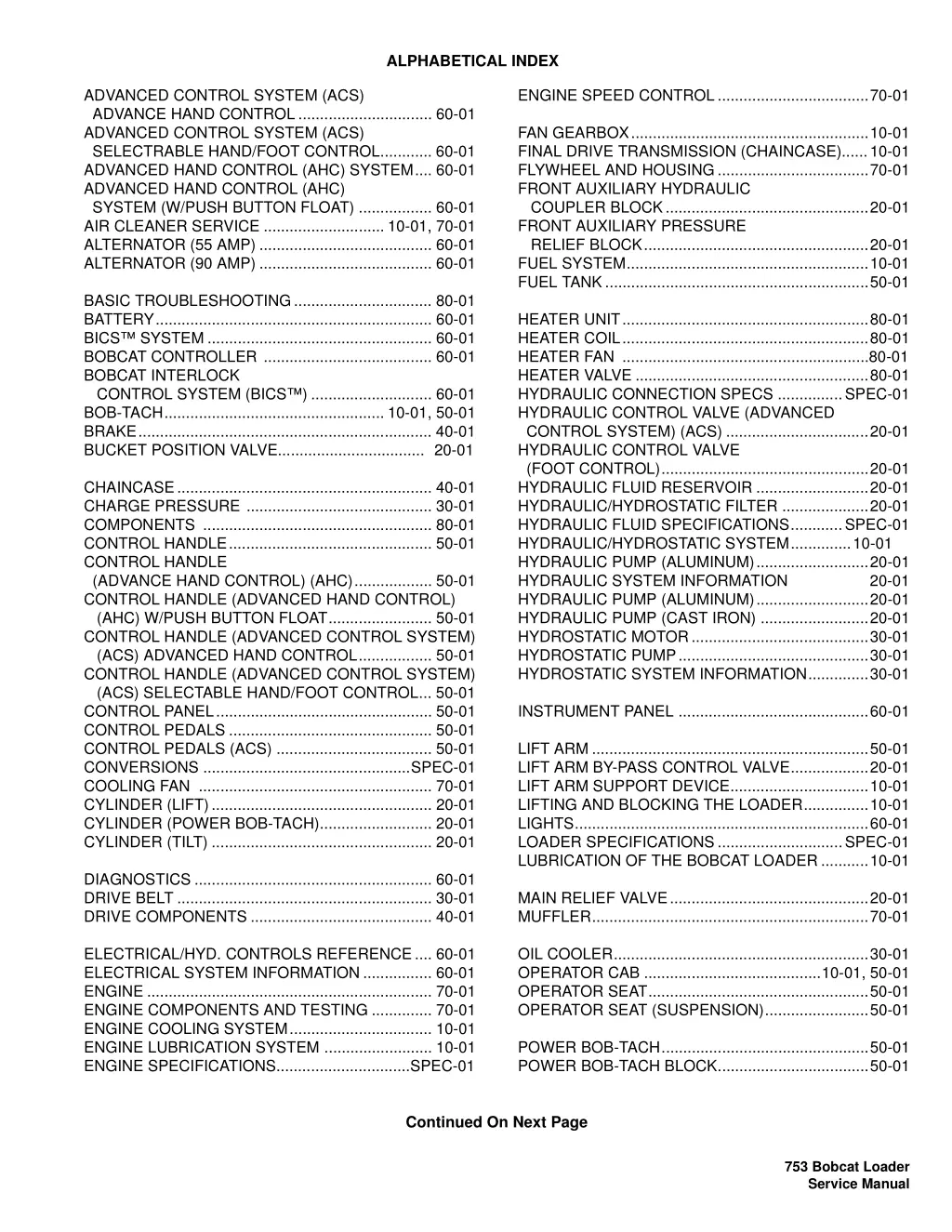
ALPHABETICAL INDEX ENGINE SPEED CONTROL...................................70-01 ADVANCED CONTROL SYSTEM (ACS) ADVANCE HAND CONTROL............................... 60-01 ADVANCED CONTROL SYSTEM (ACS) SELECTRABLE HAND/FOOT CONTROL............ 60-01 ADVANCED HAND CONTROL (AHC) SYSTEM.... 60-01 ADVANCED HAND CONTROL (AHC) SYSTEM (W/PUSH BUTTON FLOAT) ................. 60-01 AIR CLEANER SERVICE ............................ 10-01, 70-01 ALTERNATOR (55 AMP) ........................................ 60-01 ALTERNATOR (90 AMP) ........................................ 60-01 FAN GEARBOX.......................................................10-01 FINAL DRIVE TRANSMISSION (CHAINCASE)......10-01 FLYWHEEL AND HOUSING...................................70-01 FRONT AUXILIARY HYDRAULIC COUPLER BLOCK...............................................20-01 FRONT AUXILIARY PRESSURE RELIEF BLOCK....................................................20-01 FUEL SYSTEM........................................................10-01 FUEL TANK.............................................................50-01 BASIC TROUBLESHOOTING................................ 80-01 BATTERY................................................................ 60-01 BICS SYSTEM .................................................... 60-01 BOBCAT CONTROLLER ....................................... 60-01 BOBCAT INTERLOCK CONTROL SYSTEM (BICS ) ............................ 60-01 BOB-TACH................................................... 10-01, 50-01 BRAKE.................................................................... 40-01 BUCKET POSITION VALVE.................................. 20-01 HEATER UNIT.........................................................80-01 HEATER COIL.........................................................80-01 HEATER FAN .........................................................80-01 HEATER VALVE ......................................................80-01 HYDRAULIC CONNECTION SPECS ...............SPEC-01 HYDRAULIC CONTROL VALVE (ADVANCED CONTROL SYSTEM) (ACS) .................................20-01 HYDRAULIC CONTROL VALVE (FOOT CONTROL)................................................20-01 HYDRAULIC FLUID RESERVOIR ..........................20-01 HYDRAULIC/HYDROSTATIC FILTER ....................20-01 HYDRAULIC FLUID SPECIFICATIONS............SPEC-01 HYDRAULIC/HYDROSTATIC SYSTEM..............10-01 HYDRAULIC PUMP (ALUMINUM)..........................20-01 HYDRAULIC SYSTEM INFORMATION HYDRAULIC PUMP (ALUMINUM)..........................20-01 HYDRAULIC PUMP (CAST IRON) .........................20-01 HYDROSTATIC MOTOR.........................................30-01 HYDROSTATIC PUMP............................................30-01 HYDROSTATIC SYSTEM INFORMATION..............30-01 CHAINCASE........................................................... 40-01 CHARGE PRESSURE ........................................... 30-01 COMPONENTS ..................................................... 80-01 CONTROL HANDLE............................................... 50-01 CONTROL HANDLE (ADVANCE HAND CONTROL) (AHC).................. 50-01 CONTROL HANDLE (ADVANCED HAND CONTROL) (AHC) W/PUSH BUTTON FLOAT........................ 50-01 CONTROL HANDLE (ADVANCED CONTROL SYSTEM) (ACS) ADVANCED HAND CONTROL................. 50-01 CONTROL HANDLE (ADVANCED CONTROL SYSTEM) (ACS) SELECTABLE HAND/FOOT CONTROL... 50-01 CONTROL PANEL.................................................. 50-01 CONTROL PEDALS ............................................... 50-01 CONTROL PEDALS (ACS) .................................... 50-01 CONVERSIONS ................................................SPEC-01 COOLING FAN ...................................................... 70-01 CYLINDER (LIFT)................................................... 20-01 CYLINDER (POWER BOB-TACH).......................... 20-01 CYLINDER (TILT) ................................................... 20-01 20-01 INSTRUMENT PANEL ............................................60-01 LIFT ARM ................................................................50-01 LIFT ARM BY-PASS CONTROL VALVE..................20-01 LIFT ARM SUPPORT DEVICE................................10-01 LIFTING AND BLOCKING THE LOADER...............10-01 LIGHTS....................................................................60-01 LOADER SPECIFICATIONS.............................SPEC-01 LUBRICATION OF THE BOBCAT LOADER ...........10-01 DIAGNOSTICS ....................................................... 60-01 DRIVE BELT ........................................................... 30-01 DRIVE COMPONENTS .......................................... 40-01 MAIN RELIEF VALVE..............................................20-01 MUFFLER................................................................70-01 OIL COOLER...........................................................30-01 OPERATOR CAB .........................................10-01, 50-01 OPERATOR SEAT...................................................50-01 OPERATOR SEAT (SUSPENSION)........................50-01 ELECTRICAL/HYD. CONTROLS REFERENCE.... 60-01 ELECTRICAL SYSTEM INFORMATION................ 60-01 ENGINE .................................................................. 70-01 ENGINE COMPONENTS AND TESTING .............. 70-01 ENGINE COOLING SYSTEM................................. 10-01 ENGINE LUBRICATION SYSTEM ......................... 10-01 ENGINE SPECIFICATIONS...............................SPEC-01 POWER BOB-TACH................................................50-01 POWER BOB-TACH BLOCK...................................50-01 Continued On Next Page 753 Bobcat Loader Service Manual
https://www.ebooklibonline.com Hello dear friend! Thank you very much for reading. Enter the link into your browser. The full manual is available for immediate download. https://www.ebooklibonline.com
ALPHABETICAL INDEX (CONTD) RADIATOR...............................................................70-01 REAR AUXILIARY DIVERTER VALVE (DUAL SHUTTLE) .................................................50-01 REAR AUXILIARY DIVERTER VALVE (SINGLE SHUTTLE)..............................................50-01 REAR DOOR ..........................................................50-01 REAR GRILL ..........................................................50-01 RECONDITIONING THE ENGINE ..........................70-01 REGULAR MAINTENANCE ....................................80-01 REMOTE START.....................................................10-01 RPM SENSOR.........................................................70-01 SEAT BAR............................................................... 50-01 SEAT BAR SENSOR............................................... 60-01 SELECT VALVE ......................................................20-01 SERVICE SCHEDULE.............................................10-01 SPARK ARRESTOR MUFFLER..............................10-01 STARTER (NIPPONDENSO) ..................................60-01 STARTER (VALEO).................................................60-01 SYSTEM TROUBLESHOOTING CHART ...............80-01 TIRE MAINTENANCE..............................................10-01 TORQUE SPECIFICATIONS FOR BOLTS........SPEC-01 TOWING THE LOADER..........................................10-01 TRACTION LOCK....................................................60-01 TRANSPORTING THE LOADER ............................10-01 TROUBLESHOOTING.............................................70-01 753 Bobcat Loader Service Manual
SAFETY & MAINTENANCE CONTENTS FOREWORD. . . . . . . . . . . . . . . . . . . . . . . . . . . . . . . . . . . . . . . . . . . II HYDRAULIC SYSTEM SAFETY INSTRUCTIONS . . . . . . . . . . . . . . . . . . . . . . . . . . . . . . . . V SERIAL NUMBER LOCATIONS . . . . . . . . . . . . . . . . . . . . . . . . . . . .IX DELIVERY REPORT. . . . . . . . . . . . . . . . . . . . . . . . . . . . . . . . . . . . .IX HYDROSTATIC SYSTEM LOADER IDENTIFICATION . . . . . . . . . . . . . . . . . . . . . . . . . . . . . . . X SAFETY AND MAINTENANCE. . . . . . . . . . . . . . . . . . . . . . . . . .10-01 DRIVE SYSTEM HYDRAULIC SYSTEM . . . . . . . . . . . . . . . . . . . . . . . . . . . . . . . .20-01 HYDROSTATIC SYSTEM . . . . . . . . . . . . . . . . . . . . . . . . . . . . . .30-01 MAIN FRAME DRIVE SYSTEM . . . . . . . . . . . . . . . . . . . . . . . . . . . . . . . . . . . . .40-01 MAIN FRAME . . . . . . . . . . . . . . . . . . . . . . . . . . . . . . . . . . . . . . .50-01 ELECTRICAL SYSTEM & ANALYSIS ELECTRICAL SYSTEM & ANALYSIS. . . . . . . . . . . . . . . . . . . . .60-01 ENGINE SERVICE . . . . . . . . . . . . . . . . . . . . . . . . . . . . . . . . . . .70-01 ENGINE SERVICE ENGINE HEATER . . . . . . . . . . . . . . . . . . . . . . . . . . . . . . . . . . . . . . . . . . .80-01 SPECIFICATIONS. . . . . . . . . . . . . . . . . . . . . . . . . . . . . . . . . SPEC-01 HEATER SPECIFICATIONS SPECIFICATIONS 753 Bobcat Loader Service Manual I
FOREWORD This manual is for the Bobcat loader mechanic. It provides necessary servicing and adjustment procedures for the Bobcat loader and its component parts and systems. Refer to the Operation & Maintenance Manual for operating instructions, starting procedure, daily checks, etc. A general inspection of the following items must be made after the loader has had service or repair: 1. Check that the ROPS/FOPS (Including side screens) is in good condition and is not modified. 9. The parking brake must function correctly. 2. Check that ROPS mounting hardware is tightened and is Bobcat approved. 10. Enclosure door latches must open and close freely. 3. The seat belt must be correctly installed, functional and in good condition. 11. Bob-Tach linkages correctly and be in good condition. wedges must and function 4. The correctly adjusted, clean and lubricated. seat bar must be 12. Safety treads must be in good condition. 5. Check lift arm support device, replace if damaged. 13. Check for correct function of indicator lamps (Optional on some models). 6. Machine legible and in the correct location. signs must be 14. Check hydraulic fluid level, engine oil level and fuel supply. 7. Steering levers and foot pedals must return to neutral. 15. Inspect hydraulic fluid leaks. for fuel, oil or 8. Check for correct function of the work lights 16. Lubricate the loader. 753 Bobcat Loader Service Manual II
17. Check the condition of the battery and cables. 22. Operate the loader and check all functions. 18. Inspect the air cleaner for damage or leaks. Check the condition of the element. 23. Check modification not completed. for any field 19. Check the electrical charging system. 24. Check for correct function of the Bobcat Interlock Control System (BICS ) before the machine is returned to the customer. Recommend to the owner that all necessary corrections be made before the machine is returned to service. 20. Check tires for wear and pressure. 21. Inspect for loose or broken parts or connections. CALIFORNIA PROPOSITION 65 WARNING Diesel engine exhaust and some of its constituents are known to the State of California to cause cancer, birth defects and other reproductive harm. 753 Bobcat Loader Service Manual III
SAFETY INSTRUCTIONS The following publications provide information on the safe use and maintenance of the Bobcat machine and attachments: Safety Alert Symbol The Delivery Report is used to assure that complete instructions have been given to the new owner and that the machine is in safe operating condition. This symbol with a warning statement means: Warning, be alert! Your safety is involved! Carefully read the message that follows. The Operation & Maintenance Manual delivered with the machine or attachment contains operating information as well as routine maintenance and service procedures. It is a part of the machine and can be stored in a container provided on the machine. Replacement Operation & Maintenance Manuals can be ordered from your Bobcat dealer. WARNING Instructions are necessary before operating or servicing machine. Read and understand the Operation & Maintenance Handbook and signs (decals) on machine. Follow warnings and instructions in the manuals when making repairs, adjustments or servicing. Check for correct function after adjustments, repairs or service. Untrained operators and failure to follow instructions can cause injury or death. Machine signs (decals) instruct on the safe operation and care of your Bobcat machine or attachment. The signs and their locations are shown in the Operation & Maintenance Manual. Replacement signs are available from your Bobcat dealer. Manual, Operator s An Operator s Handbook fastened to the operator cab. It s brief instructions are convenient to the operator. The handbook is available from your dealer in an English edition or one of many other languages. See your Bobcat dealer for more information on translated versions. W-2003-0903 WARNING The AEM Safety Manual delivered with the machine gives general safety information. Warnings on the machine and in the manuals are for your safety. Failure to obey warnings can cause injury or death. The Service Manual and Parts Manual are available from your dealer for use by mechanics to do shop- type service and repair work. W-2044-1285 The Skid-Steer Loader Operator Training Course is available through your www.training.bobcat.com or www.bobcat.com. This course is intended to provide rules and practices of correct operation of the Skid-Steer Loader. The course is available in English and Spanish versions. local dealer or at IMPORTANT This notice identifies procedures which must be followed to avoid damage to the machine. I-2019-0284 Service Safety Training Courses are available from your Bobcat dealer or at www.training.bobcat.com or www.bobcat.com. They provide information for safe and correct service procedures. The Skid-Steer Loader Safety Video is available from your Bobcat dealer or at www.training.bobcat.com or www.bobcat.com. SI SSL-0206 SM 753 Bobcat Loader Service Manual V
SAFETY INSTRUCTIONS (CONTD) The dealer and owner/operator review the recommended uses of the product when delivered. If the owner/operator will be using the machine for a different application(s) he or she must ask the dealer for recommendations on the new use. Call Before You Dig 1-888-258-0808 When you call, you will be directed to a location in your state/city for information about buried lines (telephone, cable TV, water, sewer, gas, etc.) SI SSL-0206 SM 753 Bobcat Loader Service Manual VI
Use the procedure in the Operation & Maintenance Manual for connecting the battery and for jump starting. SAFETY INSTRUCTIONS (CONT D) Fire Prevention The machine and attachments have components that are at high temperature under normal operating conditions. The primary source of high temperatures is the engine and exhaust system. The electrical system, if damaged or incorrectly maintained, can be a source of arcs or sparks. Use the procedure in the Operation & Maintenance Manual for cleaning the spark arrestor muffler (if equipped). Figure 1 Flammable debris (leaves, straw, etc.) must be removed regularly. If flammable debris is allowed to accumulate, it will increase fire hazard. Clean often to avoid this accumulation. Flammable compartment is a potential hazard. debris in the engine The spark arrestor muffler is designed to control the emission of hot particles from the engine and exhaust system, but the muffler and the exhaust gases are still hot. Do not use the machine where exhaust, arcs, sparks or hot components can contact flammable material, explosive dust or gases. The operator cab, engine compartment, and engine cooling system must be inspected every day and cleaned if necessary to prevent fire hazard and overheating. Know where fire extinguishers and first aid kits are located and how to use them. Fire extinguishers are available from your Bobcat dealer [Figure 1]. Check all electrical wiring and connections for damage. Keep the battery terminals clean and tight. Repair or replace any damaged part. Check fuel and hydraulic tubes, hoses and fittings for damage and leakage. Never use open flame or bare skin to check for leaks. Tighten or replace any parts that show leakage. Always clean fluid spills. Do not use gasoline or diesel fuel for cleaning parts. Use commercial nonflammable solvents. Do not use ether or starting fluids on any engine which has glow plugs. These starting aids can cause explosion and injure you or bystanders. Always clean the machine, disconnect the battery, and disconnect the wiring from the controllers before welding. Cover rubber hoses, battery and all other flammable parts. Keep a fire extinguisher near the machine when welding. Have good ventilation when grinding or welding painted parts. Wear a dust mask when grinding painted parts. Toxic dust or gas can be produced. Stop the engine and let it cool before adding fuel. NO SMOKING! SI SSL-0206 SM 753 Bobcat Loader Service Manual VII
Engine Serial Number SERIAL NUMBER LOCATIONS Always use the serial number of the loader when requesting service information or when ordering parts. Early or later models (identification made by serial number) may use different parts, or it may be necessary to use a different procedure in doing a specific service operation. Figure 3 Loader Serial Number Figure 2 N-20521 The engine serial number is in the location shown [Figure 3]. DELIVERY REPORT Figure 4 N-20515 The loader serial number plate is located on theoutside of the loader frame [Figure 2]. Explanation of loader Serial Number: XXXX XXXXX Model 1.-Model/ Engine Combination Model 2.-Production Sequence (Series) 1. The four digit Model/Engine Combination Module number identifies the model number and engine combination. B-16315 The Delivery Report must be filled out by the dealer and signed by the owner or operator when the Bobcat loader is delivered. An explanation of the form must be given to the owner. Make sure it is filled out completely [Figure 4]. 2. The five digit Production Sequence Number identifies the order which the loader is produced. 753 Bobcat Loader Service Manual IX
LOADER IDENTIFICATION FRONT LIGHTS OPERATOR SEAT WITH SEAT BELT GRAB HANDLES REAR AUXILIARY QUICK COUPLERS STEERING LEVER TILT CYLINDER +BUCKET FRONT AUXILIARY QUICK COUPLERS SAFETY TREAD BUCKET STEPS OPERATOR CAB (ROPS & FOPS) REAR WINDOW SEAT BAR REAR GRILL LIFT ARM LIFT ARM SUPPORT DEVICE LIFT CYLINDERS TAIL REAR LIGHT *TIRES REAR DOOR OPTIONAL OR FIELD ACCESSORY (Not Standard Equipment) * TIRES - Flotation tires (Optional) are shown. The Bobcat loader is factory equipped with standard tires. + BUCKET - Several different buckets and other attachments are available for the Bobcat loader. ROPS, FOPS - Roll Over Protective Structure, per SAE J1040 and ISO 3471, and Falling Object Protective Structure per SAE J1043 and ISO 3449, Level I. Level II is available. The Bobcat loader is base-equipped with a standard operator cab as shown. Extra insulated cab is available as an option (Reduced noise level). 753 Bobcat Loader Service Manual X
SAFETY AND MAINTENANCE AIR CLEANER SERVICE . . . . . . . . . . . . . . . . . . . . . . . . . . . . 10-80-1 Checking . . . . . . . . . . . . . . . . . . . . . . . . . . . . . . . . . . . . . . 10-80-1 Replacing Filter Element(s) . . . . . . . . . . . . . . . . . . . . . . . . 10-80-2 SAFETY AND MAINTENANCE BOB-TACH . . . . . . . . . . . . . . . . . . . . . . . . . . . . . . . . . . . . . . 10-150-1 Inspection And Maintenance . . . . . . . . . . . . . . . . . . . . . . 10-150-1 ENGINE COOLING SYSTEM. . . . . . . . . . . . . . . . . . . . . . . . . 10-90-1 Checking The Coolant Level . . . . . . . . . . . . . . . . . . . . . . . 10-90-1 Cleaning The Cooling System . . . . . . . . . . . . . . . . . . . . . . 10-90-1 Replacing The Coolant . . . . . . . . . . . . . . . . . . . . . . . . . . . 10-90-2 DRIVE SYSTEM ENGINE LUBRICATION SYSTEM . . . . . . . . . . . . . . . . . . . . 10-110-1 Checking Engine Oil . . . . . . . . . . . . . . . . . . . . . . . . . . . . 10-110-1 Oil Chart. . . . . . . . . . . . . . . . . . . . . . . . . . . . . . . . . . . . . . 10-110-1 Replacing Oil And Filter. . . . . . . . . . . . . . . . . . . . . . . . . . 10-110-1 FAN GEARBOX. . . . . . . . . . . . . . . . . . . . . . . . . . . . . . . . . . . 10-140-1 Checking And Maintaining. . . . . . . . . . . . . . . . . . . . . . . . 10-140-1 ELECTRICAL SYSTEM & ANALYSIS FINAL DRIVE TRANSMISSION (CHAINCASE) . . . . . . . . . . 10-130-1 Checking And Adding Oil. . . . . . . . . . . . . . . . . . . . . . . . . 10-130-1 Removing The Oil . . . . . . . . . . . . . . . . . . . . . . . . . . . . . . 10-130-1 ENGINE SERVICE FUEL SYSTEM . . . . . . . . . . . . . . . . . . . . . . . . . . . . . . . . . . . 10-100-1 Filling the Fuel Tank. . . . . . . . . . . . . . . . . . . . . . . . . . . . . 10-100-1 Fuel Filter. . . . . . . . . . . . . . . . . . . . . . . . . . . . . . . . . . . . . 10-100-2 Fuel Specifications. . . . . . . . . . . . . . . . . . . . . . . . . . . . . . 10-100-1 Removing Air From The Fuel System . . . . . . . . . . . . . . . 10-100-3 SPECIFICATIONS HYDRAULIC/HYDROSTATIC SYSTEM . . . . . . . . . . . . . . . . 10-120-1 Breather Cap . . . . . . . . . . . . . . . . . . . . . . . . . . . . . . . . . . 10-120-4 Checking And Adding Fluid . . . . . . . . . . . . . . . . . . . . . . . 10-120-1 Replacing Hydraulic Fluid . . . . . . . . . . . . . . . . . . . . . . . . 10-120-3 Replacing Hydraulic/Hydrostatic Filter. . . . . . . . . . . . . . . 10-120-1 Replacing Hydrostatic Motor Case Drain Filter(s) . . . . . . 10-120-2 LIFT ARM SUPPORT DEVICE. . . . . . . . . . . . . . . . . . . . . . . . 10-20-1 Installing Lift Arm Support Device . . . . . . . . . . . . . . . . . . . 10-20-1 Removing The Lift Arm Support Device. . . . . . . . . . . . . . . 10-20-2 LIFTING AND BLOCKING THE LOADER . . . . . . . . . . . . . . . 10-10-1 Procedure . . . . . . . . . . . . . . . . . . . . . . . . . . . . . . . . . . . . . 10-10-1 Continued On Next Page 753 Bobcat Loader Service Manual 10-01
SAFETY AND MAINTENANCE (CONTD) LUBRICATION OF THE BOBCAT LOADER. . . . . . . . . . . . . 10-160-1 Procedure . . . . . . . . . . . . . . . . . . . . . . . . . . . . . . . . . . . . 10-160-1 OPERATOR CAB . . . . . . . . . . . . . . . . . . . . . . . . . . . . . . . . . . 10-30-1 Description. . . . . . . . . . . . . . . . . . . . . . . . . . . . . . . . . . . . . 10-30-1 Emergency Exit . . . . . . . . . . . . . . . . . . . . . . . . . . . . . . . . . 10-30-3 Lowering The Operator Cab . . . . . . . . . . . . . . . . . . . . . . . 10-30-2 Raising The Operator Cab. . . . . . . . . . . . . . . . . . . . . . . . . 10-30-1 REMOTE START. . . . . . . . . . . . . . . . . . . . . . . . . . . . . . . . . . . 10-60-1 Procedure . . . . . . . . . . . . . . . . . . . . . . . . . . . . . . . . . . . . . 10-60-1 SERVICE SCHEDULE . . . . . . . . . . . . . . . . . . . . . . . . . . . . . . 10-70-1 Chart . . . . . . . . . . . . . . . . . . . . . . . . . . . . . . . . . . . . . . . . . 10-70-1 SPARK ARRESTOR MUFFLER . . . . . . . . . . . . . . . . . . . . . . 10-180-1 Servicing . . . . . . . . . . . . . . . . . . . . . . . . . . . . . . . . . . . . . 10-180-1 TIRE MAINTENANCE. . . . . . . . . . . . . . . . . . . . . . . . . . . . . . 10-170-1 Mounting . . . . . . . . . . . . . . . . . . . . . . . . . . . . . . . . . . . . . 10-170-1 Rotating . . . . . . . . . . . . . . . . . . . . . . . . . . . . . . . . . . . . . . 10-170-1 Wheel Nuts . . . . . . . . . . . . . . . . . . . . . . . . . . . . . . . . . . . 10-170-1 TOWING THE LOADER . . . . . . . . . . . . . . . . . . . . . . . . . . . . . 10-50-1 Procedure . . . . . . . . . . . . . . . . . . . . . . . . . . . . . . . . . . . . . 10-50-1 TRANSPORTING THE BOBCAT LOADER . . . . . . . . . . . . . . 10-40-1 Procedure . . . . . . . . . . . . . . . . . . . . . . . . . . . . . . . . . . . . . 10-40-1 753 Bobcat Loader Service Manual 10-02
LIFTING AND BLOCKING THE LOADER Figure 10-10-2 Procedure Figure 10-10-1 P-31849 Put floor jack under the rear of the loader [Figure 10-10- 2]. B-7023A Lift the rear of the loader and install jackstands [Figure 10-10-2]. WARNING Figure 10-10-3 Instructions are necessary before operating or servicing machine. Read and understand the Operation & Maintenance Manual, Handbook and signs (decals) on machine. Follow warnings and instructions in the manuals when making repairs, adjustments or servicing. Check for correct function after adjustments, repairs or service. Untrained operators and failure to follow instructions can cause injury or death. W-2003-0199 Always park the loader on a level surface. P-3868 WARNING Put the floor jack under the front of the loader [Figure 10- 10-3]. Put jackstands under the front axles and rear corners of the frame before running the engine for service. Failure to use jackstands can allow the machine to fall or move and cause injury or death. Lift the front of the loader and put jackstands under the axle tubes [Figure 10-10-3]. NOTE: Make sure the jackstands do not touch the tires. Make sure tires clear floor or any obstacles. W-2017-0286 753 Bobcat Loader Service Manual 10-10-1
LIFT ARM SUPPORT DEVICE Figure 10-20-1 Installing Lift Arm Support Device 1 2 WARNING N-20526 P-31849 Never work on a machine with the lift arms up unless the lift arms are secured by an approved lift arm support device. Failure to use an approved lift arm support device can allow the lift arms or attachment to fall and cause injury or death. Put jackstands under the rear corners of the loader frame (Inset) [Figure 10-20-1]. Disconnect the spring from the lift arm support device retaining pin (Item 1). Support the lift arm support device (Item 2) [Figure 10-20-1] with your hand and remove the retaining pin. W-2059-0598 WARNING Figure 10-20-2 Service lift arm support device if damaged or if parts are missing. Using a damaged lift arm support or with missing parts can cause lift arms to drop causing injury or death. 1 W-2271-1197 N-20525 Lower the lift arm support device on top of the lift cylinder. Hook the free end of the spring (Item 1) [Figure 10-20-2] to the lift arm support device so there will be no interference with the support device engagement. With the operator in the seat, seat belt fastened and seat bar lowered, start the engine. 753 Bobcat Loader Service Manual 10-20-1
With the operator in the seat, seat belt fastened and seat bar lowered, start the engine. LIFT ARM SUPPORT DEVICE (CONT D) Installing Lift Arm Support Device (Cont d) Raise the lift arms a small amount and the spring will lift the support device off the lift cylinder rod. Lower the lift arms. Stop the engine. Figure 10-20-3 Raise the seat bar and move pedals until both pedals lock. Disconnect the spring from the bracket. Figure 10-20-5 1 2 1 N-20524 Raise the lift arms, until the lift arm support device drops onto the lift cylinder rod [Figure 10-20-3]. Lower the lift arms slowly until the support device is held between the lift arm and the lift cylinder. Stop the engine. Raise the seat bar and move pedals until both pedals lock. N-20526 Install pin (Item 1) [Figure 10-20-3] into the rear of the lift arm support device below the cylinder rod. Raise the support device into storage position and insert pin (Item 1) through lift arm support device (Item 2) [Figure 10-20-5] and bracket. Connect spring to pin. Removing The Lift Arm Support Device Remove jackstands. Figure 10-20-4 1 N-20523 Remove the pin from the lift arm support device. Connect the spring (Item 1) [Figure 10-20-4] from the lift arm support device to the bracket below the lift arms. 753 Bobcat Loader Service Manual 10-20-2
Figure 10-30-1 OPERATOR CAB Description The Bobcat loader has an operator cab (ROPS and FOPS) as standard equipment to protect the operator from rollover and falling objects. Check with your dealer if the operator cab has been damaged. The seat belt must be worn for roll over protection. ROPS/FOPS - Roll Over Protective Structure per SAE J1040 and ISO 3471, and Falling Object Protective Structure per SAE J1043 and ISO 3449, Level I. Level II is available. Level I - Protection from falling bricks, small concrete blocks, and hand tools encountered in operations such as highway maintenance, landscaping, and other construction site services. P-31849 Install jackstands under the rear of the loader frame [Figure 10-30-1]. Level II - Protection from falling trees, rocks; for machines involved in site clearing, overhead demolition or forestry. Raising The Operator Cab Always stop the engine before raising or lowering the cab. Stop the loader on a level surface. Lower the lift arms. If the lift arms must be up while raising the operator cab, install the lift arm support device. (See Installing Lift Arm Support Device on Page 10-20-1.) WARNING Never modify operator cab by welding, grinding, drilling holes or adding instructed to do so by Bobcat. Changes to the cab can cause loss of operator protection from rollover and falling objects, and result in injury or death. attachments unless W-2069-1299 753 Bobcat Loader Service Manual 10-30-1
Advanced Control System (ACS) and Advanced Hand Controls (AHC) Only OPERATOR CAB (CONT D) Raising The Operator Cab (Cont d) Lowering The Operator Cab Figure 10-30-2 Figure 10-30-4 N-20520 N-20519 N-20120 N-20608 Loosen the nut (both sides) at the front corners of the operator cab [Figure 10-30-2]. Always stop the engine before raising or lowering the cab. Remove the nuts and plates [Figure 10-30-2] (both sides). NOTE: Make sure the seat bar is fully raised or lowered when lowering the cab. Always use the grab handles to lower the cab. Figure 10-30-3 Pull down on the bottom of the operator cab until it stops at the latching mechanism [Figure 10-30-4]. Release the latching mechanism (Inset) [Figure 10-30-4] and pull the cab all the way down. Figure 10-30-5 N-20608 Lift on the grab handle and bottom of the operator cab slowly until the cab is all the way up and the latching mechanism engages [Figure 10-30-3]. N-20519 N-20519 Install the plates and nuts [Figure 10-30-5] (both sides). Tighten the nuts to 40-50 ft.-lbs. (54-68 Nm) torque. 753 Bobcat Loader Service Manual 10-30-2
Figure 10-30-8 OPERATOR CAB (CONT D) Emergency Exit Figure 10-30-6 N-20171 Front Door (If Equipped) N-19386 NOTE: When an Operator Cab Enclosure Kit is installed, the window of the front door can be used as an emergency exit. [Figure 10-30-8] The front opening on the operator cab and rear window provide exits. Pull the plastic loop at the top of the window in the front door to remove the rubber cord [Figure 10-30-8]. Rear Window (If Equipped) Pull on the tag on the top of the rear window to remove the rubber cord [Figure 10-30-6]. Figure 10-30-9 Figure 10-30-7 X P-30255 Push the window out with your foot [Figure 10-30-9] at any corner of the window. N-20606 Push the rear window out of the rear of the operator cab. Exit through the front door. Exit through the rear of the operator cab [Figure 10-30- 7]. 753 Bobcat Loader Service Manual 10-30-3
TRANSPORTING THE BOBCAT LOADER Figure 10-40-2 Procedure WARNING Adequately designed ramps of sufficient strength are needed to support the weight of the machine when loading onto a transport vehicle. Wood ramps can break and cause personal injury. W-2058-0494 N-19048A N-19073 Figure 10-40-1 1 N-20659 N-20527 Be sure the transport and towing vehicles are of adequate size and capacity (See Machine Dimensions on Page SPEC-10-1.) A loader with an empty bucket or no attachment must be loaded backward onto the transport vehicle [Figure 10- 40-1]. 6707867 Use the following procedure to fasten the Bobcat loader to the transport vehicle to prevent the loader from moving during sudden stops or when going up or down slopes [Figure 10-40-2]. The rear of the trailer must be blocked or supported (Item 1) [Figure 10-40-1] when loading or unloading the loader to prevent the front end of the trailer from raising up. Lower the bucket or attachment to the floor. Stop the engine. Engage the parking brake. Install chains at the front and rear loader tie down positions (Inset) [Figure 10-40-2]. Fasten each end of the chain to the transport vehicle. 753 Bobcat Loader Service Manual 10-40-1
Figure 10-50-2 TOWING THE LOADER Procedure Figure 10-50-1 1 1 N-18409 Press the TRACTION LOCK OVERRIDE Button (Item 1) [Figure 10-50-2]. N-18410 Tow the Bobcat at 2 MPH (3,2 km/hr) or less for not more than 25 feet (7,6 meters). To prevent damage to the loaders hydrostatic system, the loader must be towed only a short distance at slow speed. (Example: Moving the loader onto a transport vehicle). If the electrical system is not functioning or the engine does not run part of the brake system must be disassembled to move the loader. (See TRACTION LOCK on Page 60-110-1.) The towing chain (or cable) must be rated at 1 & 1/2 times the weight of the loader. (See Machine Dimensions on Page SPEC-10-1.) Turn the key switch to RUN (Item 1) [Figure 10-50-1] (Standard Panel) OR press the RUN/ENTER Button (Deluxe Panel). 753 Bobcat Loader Service Manual 10-50-1
Figure 10-60-3 REMOTE START Procedure Figure 10-60-1 1 1 P-28823 Lift and block the loader. (See LIFTING AND BLOCKING THE LOADER on Page 10-10-1.) N-20862 Raise the lift arms (if required by the procedure) and install an approved lift arm support device. (See Installing Lift Arm Support Device on Page 10-20-1.) The tool listed will be needed to do the following procedure: MEL1563: Remote Start Tool Kit Raise the operator cab (if required by the procedure). (See Raising The Operator Cab on Page 10-30-1.) The remote start (Item 1) [Figure 10-60-1] is required when the operator cab is in the raised position for service and the service technician needs to turn the key switch on or start the engine. Example: adjusting the steering linkage. Open the rear door of the loader. Remove the plug (Item 1) [Figure 10-60-2] /or disconnect the attachment control harness (Item 1) [Figure 10-60-3] if connected. Figure 10-60-2 1 P-28793 753 Bobcat Loader Service Manual 10-60-1
REMOTE START (CONTD) WARNING Procedure (Cont'd) Figure 10-60-4 AVOID INJURY OR DEATH With the 7-pin connector plugged into the loader and Remote Start Key Switch in the OFF position, the loader can still be started from the operator panel inside the cab. Placing the key switch of the remote start tool in the run position disconnects the operator panel key switch from the start circuit. If the service technician will be working the engine area it is important to remove the operator panel keys. 1 W-2357-0899 Figure 10-60-5 P-28806 Connect the remote start tool to the engine harness connector (Item 1) [Figure 10-60-4]. 1 NOTE: The key switch on the right-hand side operator panel must be in the off position or the Remote Start Kit will not operate. N-20861 The remote start tool (Item 1) [Figure 10-60-5] has three rocker switches. 753 Bobcat Loader Service Manual 10-60-2
S/N 515842310 and Above REMOTE START (CONT D) Procedure (Cont'd) Figure 10-60-7 Figure 10-60-6 1 2 3 1 P-43215 N-20863 If your loader is equipped with the front auxiliary coupler block (Item 1) [Figure 10-60-7], push the couplers towards the block and hold for five seconds to release the front auxiliary pressure. The traction lock switch (Item 1) [Figure 10-60-6] is used to turn traction lock on or off. Push the switch to the override position. The switch will illuminate to indicate traction lock OVERRIDE, in this position the wheels are able to turn. To release the rear auxiliary coupler pressure, use the pressure release button (Item 3) [Figure 10-60-6] on the remote start tool. The maximum flow/variable flow switch (Item 2) [Figure 10-60-6] is used to activate the auxiliary hydraulics. Pressing the switch once will activate variable flow. Pressing the switch again will activate maximum flow. The switch will illuminate to indicate which flow rate is active. Pressing the switch a third time will turn the flow OFF. The switch is used when checking pressures and flow rate. S/N 515842309 and Below The auxiliary pressure release (Item 3) [Figure 10-60-6] is used to release hydraulic pressure to the front and/or rear auxiliary couplers. To release pressure; push and hold the switch for three seconds. NOTE: With the engine running; pushing and holding the pressure release switch this will cause the engine to stop in three seconds. To relieve the pressure; continue to press the switch after the engine has stopped. 753 Bobcat Loader Service Manual 10-60-3
SERVICE SCHEDULE Chart Maintenance work must be done at regular intervals. Failure to do so will result in excessive wear and early failures. The service schedule is a guide for correct maintenance of the Bobcat loader. Instructions are necessary before operating or servicing machine. Read and understand the Operation & Maintenance Manual, Handbook and signs (decals) on machine. Follow warnings and instructions in the manuals when making repairs, adjustments or servicing. Check for correct function after adjustments, repairs or service. Untrained operators and failure to follow instructions can cause injury or death. WARNING W-2003-0199 SERVICE SCHEDULE HOURS 8-10 ITEM SERVICE REQUIRED 1000 50 100 250 500 Engine Oil Engine Air Filter and Air System Check the oil level and add oil as needed. Check display panel for lighted icon and/or Service Code. Service only when required. Check for leaks and damaged components. Clean debris from oil cooler, radiator & grill. Check coolant level in recovery tank when engine is cold. Add 53% propylene glycol premixed with 47% water as needed. Check for damaged tires and correct air pressure. Inflate to MAXIMUM pressure shown on tire sidewall. Check the condition of seat belt. Check the seat bar and control interlocks. Clean dirt and debris from moving parts. Check for damaged signs (decals) and safety treads. Replace any signs or safety treads that are damaged or worn. Check for correct operation of all indicators and lights. Check the fastening bolts, washers and nuts. Check the condition of the cab. Lubricate with multi-purpose lithium based grease. Engine Cooling System Tires Seat Belt, Seat Bar and Control Interlocks Safety Signs and Safety Treads Indicators & Lights (Opt.) Operator Cab Lift Arms, Cylinders, Bob-Tach Pivot Pins and Wedges Fuel Filter Heater Filters Bobcat Interlock Control System (BICS ) Hydraulic Fluid, Hoses and Tubelines Final Drive Trans. (Chaincase), Foot Pedals or Hand Controls and Steering Levers Wheel Nuts Parking Brake Spark Arrestor Muffler Battery Steering Lever Pivots Engine/Hydrostatic Drive Belt Fan Drive Gearbox Alternator Belt Engine Oil and Filter Fuel Filter Bobcat Interlock Control System (BICS ) Hydraulic Reservoir Breather Cap Hyd./Hydro. Filter Hydraulic Reservoir Final Drive Trans. (Chaincase) Case Drain Filters Remove the trapped water. Clean or replace filters as needed during heating/cooling season. Check the four (4) BICS indicator lights and functions are activated. See details in this Manual. Check fluid level and add as needed. Check for damage and leaks. Repair or replace as needed. Check oil level. Check for correct operation. Repair or adjust as needed. Check for correct operation. Repair or adjust as needed. Check for loose wheel nuts and tighten to 105-115 ft.-lbs. (142-156 Nm) torque Check operation. Clean the spark chamber. Check cables, connections and electrolyte level. Add distilled water as needed. Grease two fittings. * Check for wear or damage. Adjust as needed. Check gear lube level. Add as needed. Check belt tension and adjust as needed. ^ Replace oil and filter. Use CD or better grade oil and Bobcat filter. Replace the filter element. Check the function of the lift arm by-pass control Replace the reservoir breather cap. Replace the filter element. Replace the fluid Replace the fluid Replace the filters Check wheel nut torque every 8 hours for the first 24 hours. * Inspect the new belt after first 50 hours. Replace filter element after the first 50 hours and when the transmission warning light comes ON. ^ First oil and filter change must occur at 50 hours; 250 hours thereafter. Or every 12 months. 753 Bobcat Loader Service Manual 10-70-1
AIR CLEANER SERVICE Figure 10-80-2 Checking Figure 10-80-1 1 2 1 N-18409 Press and hold the LIGHT Button (Item 1) [Figure 10-80- 2] for two seconds. P-21769A If the filter element needs replacement, the CODE [01- 17] (Air Filter Plugged) will show in the HOURMETER / CODE DISPLAY (Item 2) [Figure 10-80-2]. It is important to change the air filter element only when the Air Cleaner icon in the right panel is ON (Item 1) [Figure 10-80-1] and you hear three beeps from the alarm. Replace the inner filter every third time the outer filter is replaced or as indicated. (See Replacing Filter Element(s) on Page 10-80-2.) 753 Bobcat Loader Service Manual 10-80-1
MORE MANUALS: https://www.ebooklibonline.com/ Suggest: If the above button click is invalid. Please download this document first, and then click the above link to download the complete manual. Thank you so much for reading
AIR CLEANER SERVICE (CONTD) Figure 10-80-5 Replacing Filter Element(s) OUTER FILTER Figure 10-80-3 1 P-43240 Remove the outer filter element [Figure 10-80-5]. NOTE: Be sure all sealing surfaces are clean. P-43243 Install the new filter element and washer. Tighten the wing nut. Remove the wing nut (Item 1) [Figure 10-80-3] and remove the dust cover. NOTE: Be sure sealing washer is in place on each wing nut [Figure 10-80-4]. Figure 10-80-4 Install the dust cover and tighten the wing nut. Check the air intake hose and the air cleaner housing for damage. Make sure all connections are tight. 1 P-43239 Remove the wing nut (Item 1) [Figure 10-80-4] from the outer filter element. 753 Bobcat Loader Service Manual 10-80-2
https://www.ebooklibonline.com Hello dear friend! Thank you very much for reading. Enter the link into your browser. The full manual is available for immediate download. https://www.ebooklibonline.com


")


")


")


 and Advanced Hand")


")


")