BOBCAT 753 SKID STEER LOADER Service Repair Manual Instant Download SN 513911001-513911148
Please open the website below to get the complete manualnn// n

Download Presentation

Please find below an Image/Link to download the presentation.
The content on the website is provided AS IS for your information and personal use only. It may not be sold, licensed, or shared on other websites without obtaining consent from the author. Download presentation by click this link. If you encounter any issues during the download, it is possible that the publisher has removed the file from their server.
E N D
Presentation Transcript
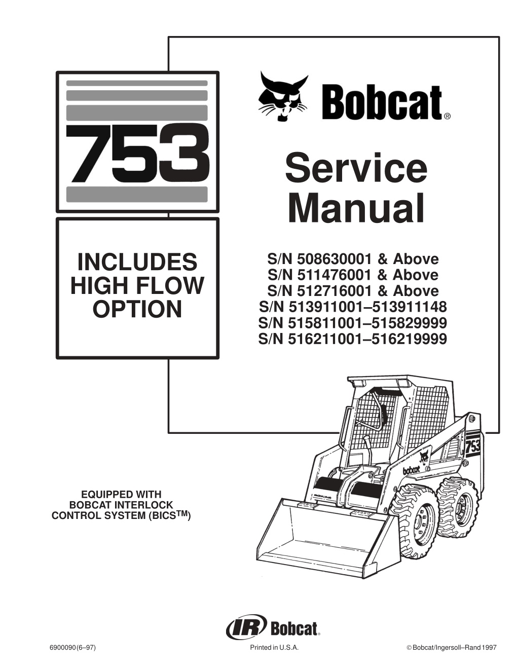
Service Manual INCLUDES HIGH FLOW OPTION S/N 508630001 & Above S/N 511476001 & Above S/N 512716001 & Above S/N 513911001 513911148 S/N 515811001 515829999 S/N 516211001 516219999 EQUIPPED WITH BOBCAT INTERLOCK CONTROL SYSTEM (BICSTM) Bobcat/Ingersoll Rand 1997 6900090 (6 97) Printed in U.S.A.
MAINTENANCE SAFETY Instructions are necessary before operating or servicing machine. Read and understand the Operation & Maintenance Manual, Operator s Handbook and signs (decals) on machine. Follow warnings and instructions in the manuals when making repairs, adjustments or servicing. Check for correct function after adjustments, repairs or service. Untrained operators and failure to follow instructions can cause injury or death. WARNING W-2003-0903 Safety Alert Symbol: This symbol with a warning statement, means: Warning, be alert! Your safety is involved! Carefully read the message that follows. CORRECT CORRECT CORRECT B-10731a B-12365 B-7469 Never service the Bobcat Skid- Steer Loader without instructions. Use the correct procedure to lift or lower operator cab. Cleaning and maintenance are required daily. WRONG WRONG WRONG B-11799 B-15231 B-15280 Have good ventilation when welding or grinding painted parts. Wear dust mask when grinding painted parts. Toxic dust and gas can be produced. Avoid exhaust fume leaks which can kill without warning. Exhaust system must be tightly sealed. Disconnecting or loosening any hydraulic tubeline, hose, fitting, component or a part failure can cause lift arms to drop. Do not go under lift arms when raised unless supported approved lift arm support device. Replace it if damaged. Never work on loader with lift arms up unless lift arms are held by an approved lift arm support device. Replace if damaged. Never modify equipment or add attachments not approved by Bobcat Company. by an WRONG WRONG WRONG B-6580 B-6589 B-6590 B-16102 B-16102 Stop, cool and clean engine of flammable materials checking fluids. Never service or adjust loader with the engine running unless instructed to do so in the manual. Avoid contact hydraulic fluid or diesel fuel under pressure. It can penetrate the skin or eyes. Never fill fuel tank with engine running, while smoking or when near open flame. Maintenance procedures which are given in the Operation & Maintenance Manual can be performed by the owner/ operator without any specific technical training. Maintenance procedures which are not in the Operation & Maintenance Manual must be performed ONLY BY QUALIFIED BOBCAT SERVICE PERSONNEL. Always use genuine Bobcat replacement parts. The Service Safety Training Course is available from your Bobcat dealer. Keep body, jewelry and clothing away from electrical contact, hot parts and exhaust. Wear eye protection to guard from battery acid, compressed springs, fluids under pressure and flying debris when engines are running or tools are used. Use eye protection approved for type of welding. Keep rear door closed except for service. Close and latch door before operating the loader. Lead-acid flammable and explosive gases. Keep arcs, sparks, flames and lighted tobacco batteries. Batteries contain acid which burns eyes or skin on contact. Wear protective clothing. If acid contacts body, flush well with water. For eye contact flush well and get immediate attention. batteries produce before moving parts, away from with leaking medical MSW01-0805
ALPHABETICAL INDEX ACTUATORS ACTUATOR VOLTAGE TEST A.H.C. COMPONENTS A.H.C./PWM CONTROLLER A.H.C. HANDLE A.H.C. STEERING LEVER AIR CLEANER AIR CLEANER SERVICE ALTERNATOR ALTERNATOR BELT AXLE SEAL . . . . . . . . . . . . . . . . . . . . . . . . . . . . . . . . . . AXLE, SPROCKET AND BEARINGS . . . . . . . . . . . . . . . . . . . . . . . . . . . . . . . . . . . . . . . . . . . . . . . . . . . . . . . . . . . . . . . . . . . . . . . . . . . . . . . . . . . . . . . . . . . . . . . . . . . . . . . . . . . . . . . . . . . . . . . . . . . . . . . . . . . . . . . . . . . . . . . . . . . . . . . . . . . . . . . . . . . . . . . . . . . . . . . . . . . . . . . . . . . . . . . . . . . . . . . . . . . . . . . . . . . . . . . . . . . . . . . . . . . . . . . . . . . . . . . . . . . . . . . . . . . . 10 1 10 1 10 1 10 1 10 1 10 1 7 1 1 1 6 1 1 1 4 1 4 1 IDLER GEAR AND CAMSHAFT . . . . . . . . . . . . . . . . . . 7 1 LIFT ARM SUPPORT DEVICE LIFT ARMS . . . . . . . . . . . . . . . . . . . . . . . . . . . . . . . . . . . . LIFT CYLINDER(S) . . . . . . . . . . . . . . . . . . . . . . . . . . . . . LIFT LOCK BY PASS VALVE LIFTING AND BLOCKING THE LOADER LIFTING THE LOADER . . . . . . . . . . . . . . . . . . . . . . . . . LOADER SPECIFICATIONS 763 LUBRICATING THE LOADER . . . . . . . . . . . . . . . . . . . 1 1 5 1 2 1 2 1 1 1 1 1 9 1 1 1 . . . . . . . . . . . . . . . . . . . . . . . . . . . . . . . . . . . . . . . . . . . . . . . . . . . . . . . . . . . . . . . . . . . . . . . . . . . MONITOR SERVICE CODES MOTOR CARRIER . . . . . . . . . . . . . . . . . . . . . . . . . . . . . . . . . . . . . . . . . . . . . . . . . 8 1 4 1 BATTERY BICS SYSTEM CONTROLLER BICS VALVE . . . . . . . . . . . . . . . . . . . . . . . . . . . . . . . . . . BLOWER HOUSING/FAN GEARBOX BOBCAT INTERLOCK CONTROL SYSTEM (BICS ) BOB TACH . . . . . . . . . . . . . . . . . . . . . . . . . . . . . . BOSS DIAGNOSTIC TOOL BOSS INSTRUMENT PANEL . . . . . . . . . . . . . . . . . . . . . . . . . . . . . . . . . . . . 6 1 8 1 2 1 7 1 . . . . . . . . . . . . . . . . OIL COOLER OIL PUMP OPERATOR CAB OPERATOR CAB GAS CYLINDER OPERATOR SEAT OPERTION SENSING SYSTEM UNIT . . . . . . . . . . . . . . . . . . . . . . . . . . . . . . . . . . . . . . . . . . . . . . . . . . . . . . . . . . . . . . . . . . . . . . . . . . . . . . . . . . . . . . . . . . . . . . . 3 1 7 1 . . . . . . . . . . . 1 1, 5 1 . . . . . . . . . . . . 8 1, 10 1 1 1, 5 1 . . . . . . . . . . . . . . . 5 1 5 1 8 1 . . . . . . . . . . . . . . . . . . . . . . . . . . . . . . . . . . . . . . . . . . . . . . . . . . . . . . . . . . . . . . . . . 8 1 8 1 . . . . . . . . . . . . PARKING BRAKE PARKING BRAKE DISC PISTON AND CONNECTING ROD PIVOT PINS . . . . . . . . . . . . . . . . . . . . . . . . . . . . . . . . . . . . . . . . . . . . . . . . . . . . . . . . . . . . . . . . . . . . . . . . . . . . . . . . . . . . . . . . . . . . . . . . . . . . . . . . 4 1 4 1 7 1 1 1 CHAINCASE COVERS CHAINCASE FLUID CONTROL INTERLOCK LINKAGE CONTROL PANEL CONTROL PEDALS CRANKSHAFT AND BEARINGS CRANKSHAFT GEAR CYLINDER BORE CYLINDER HEAD . . . . . . . . . . . . . . . . . . . . . . . . . . . . . . . . . . . . . . . . . . . . . . . . . . . . . . . . . . . . . . . . . . . . . . . . . . . . . . . . . . . . . . . . . . . . . . . . . . . . . . . . . . . . . . . . . . . . . . . . . . . . . . . . . . . . . . . . . . . . . . . . . . . . . . . . . . . . . . . . . . . . . . . . . . . . . . . . . . . . . . . . . . . . . . . . . . . . . . . . . . . . . . . . . . . . . . . . . . . 4 1 4 1 2 1 3 1 2 1 7 1 7 1 7 1 7 1 RADIATOR REAR DOOR REAR GRILL REAR LIGHTS RELAY SWITCHES REMOTE START SWITCH ROCKER ARM AND SHAFT RPM SENSOR . . . . . . . . . . . . . . . . . . . . . . . . . . . . . . . . . . . . . . . . . . . . . . . . . . . . . . . . . . . . . . . . . . . . . . . . . . . . . . . . . . . . . . . . . . . . . . . . . . . . . . . . . . . . . . . . . . . . . . . . . . . . . . . . . . . . . . . . . . . . . . . . . . . . . . . . . . . . . . . . . . . . . . . . . . . . . . . . . . . . . . . . . . . . . . . . . . . . . . . . . . . . . . . . . . . . . . . . . . . . . . . . . . . . . . . . . . . . . . . . . 7 1 5 1 5 1 5 1 6 1 1 1 7 1 8 1 DECIMAL & MILLIMETER EQUIVALENTS DRIVE BELT . . . . . . . . . . . . . . . . . . . . . . . . . . . . . . . . . DRIVE BELT HOUSING . . . . . . . . . . . . . . . . . . . . . . . . DRIVE CHAIN . . . . . . . . . . . . . . . . . . . . . . . . . . . . . . . . . . . . . . . 9 1 1 1 3 1 4 1 SEAT BAR SEAT BAR RESTRAINT SYSTEM SEAT BAR SENSOR SEAT SENSOR . . . . . . . . . . . . . . . . . . . . . . . . . . . . . . . . SELECT VALVE (763H) . . . . . . . . . . . . . . . . . . . . . . . . . SENDER AND SENSOR . . . . . . . . . . . . . . . . . . . . . . . . SERVICE SCHEDULE . . . . . . . . . . . . . . . . . . . . . . . . . . SPARK ARRESTOR MUFFLER SPRING LOADED DRIVE BELT TENSIONER PULLEY . . . . . . . . . . . . . . . . . . . . . . . . . . . . . . . . . . . . . STANDARD INSTRUMENT PANEL STANDARD TORQUE SPECIFICATIONS FOR BOLTS . . . . . . . . . . . . . . . . . . . . . . . . . . . . . . . . . . STARTER . . . . . . . . . . . . . . . . . . . . . . . . . . . . . . . . . . . . . STEERING LINKAGE . . . . . . . . . . . . . . . . . . . . . . . . . . . SWITCH HANDLE . . . . . . . . . . . . . . . . . . . . . . . . . . . . STOPPING THE BOBCAT LOADER . . . . . . . . . . . . . . . . . . . . . . . . . . . . . . . . . . . . 5 1 1 1 8 1 8 1 2 1 8 1 1 1 1 1 ELECTRICAL/HYDRAULIC (CONTROL REF.) ELECTRICAL SYSTEM INFORMATION ENGINE . . . . . . . . . . . . . . . . . . . . . . . . . . . . . . . . . . . . . ENGINE COMPRESSION ENGINE COOLING SYSTEM ENGINE LUBRICATION SYSTEM ENGINE MUFFLER . . . . . . . . . . . . . . . . . . . . . . . . . . . ENGINE SPECIFICATIONS ENGINE SPEED CONTROL . . . . 8 1 6 1 7 1 7 1 1 1 1 1 7 1 9 1 7 1 . . . . . . . . . . . . . . . . . . . . . . . . . . . . . . . . . . . . . . . . . . . . . . . . . . . . . . . . . . . . . . . . . . . . . . . . . . . . . . . . . . . . . . . . . . . . . . . . . . . . . . . . . . . . . . . . . . . . . . . . . . . . . . . . . . . . . . . . . . . . . . . . . . . . . . . . . . . . . . . . . . . . . . 3 1 6 1 . . . . . . . . . . . . . . . FAN GEARBOX FINAL DRIVE TRANSMISSION (CHAINCASE) FIXED DRIVE BELT TENSIONER PULLEY FLYWHEEL . . . . . . . . . . . . . . . . . . . . . . . . . . . . . . . . . . FRONT LIGHTS . . . . . . . . . . . . . . . . . . . . . . . . . . . . . . FUEL CAMSHAFT . . . . . . . . . . . . . . . . . . . . . . . . . . . . FUEL INJECTION NOZZLES FUEL INJECTION PUMP FUEL SYSTEM . . . . . . . . . . . . . . . . . . . . . . . . . . . . . . . FUEL TANK . . . . . . . . . . . . . . . . . . . . . . . . . . . . . . . . . . . . . . . . . . . . . . . . . . . . . . . . . . . . . 1 1, 7 1 . . . . . . . . . . 1 1 3 1 7 1 6 1 7 1 7 1 7 1 1 1 5 1 9 1 6 1 3 1 10 1 1 1 . . . . . . . . . . . . . . . . . . . . . . . . . . . . . . . . . . . . . . . . . . . . . . . . . . . . . . . TILT LOCK VALVE TILT CYLINDER TIMING GEARS TIMING GEARCASE COVER TIRE MAINTENANCE TORQUE SPECIFICATIONS FOR LOADER TOWING THE LOADER TRACTION LOCK . . . . . . . . . . . . . . . . . . . . . . . . . . . . . . TRACTION LOCK GUIDES TRANSPORTING THE LOADER TROUBLESHOOTING . . . . . . . TROUBLESHOOTING THE BOSS & L.C.D. DISPLAY . . . . . . . . . . . . . . . . . . . . . . . . . . . . . . . . . . . . . . . . . . . . . . . . . . . . . . . . . . . . . . . . . . . . . . . . . . . . . . . . . . . . . . . . . . . . . . . . . . . . . . . . . . . . . . . . . . . . . . . . . . . . . . . . . . . . . . . . . 2 1 2 1 7 1 7 1 1 1 9 1 1 1 8 1 4 1 1 1 GLOW PLUGS . . . . . . . . . . . . . . . . . . . . . . . . . . . . . . . . 7 1 HANDLE CONTROL UNIT HYDRAULIC CONTROL VALVE HYDRAULIC CONTROL VALVE (AHC) HYDRAULIC CYLINDER IDENTIFICATION HYDRAULIC CYLINDERS HYDRAULIC FILTER HOUSING HYDRAULIC FLUID RESERVOIR HYDRAULIC/HYDROSTATIC FLUID SPECIFICATIONS HYDRAULIC/HYDROSTATIC SYSTEM HYDRAULIC PUMP . . . . . . . . . . . . . . . . . . . . . . . . . . . HYDRAULIC SYSTEM INFORMATION HYDROSTATIC DRIVE MOTOR HYDROSTATIC DRIVE MOTOR 30 SERIES HYDROSTATIC PUMP . . . . . . . . . . . . . . . . . . . . . . . . . HYDROSTATIC SYSTEM INFORMATION . . . . . . . . . . . . . . . . . . . . . . . . . . . . . . . . . . . . 10 1 2 1 10 1 2 1 2 1 2 1 2 1 . . . . . . . . . . . . . . . . . . . . . . . . . . . . . . . . . . . . . . . . . . . . . . . . . . . . . . . . . . . . . . . . . . . . . . . . . . . . . . . . . . . . . . 2 1, 3 1, 6 1, 7 1, 10 1 . . . . . . . . . . . . . . . . . . . . . . . . . . . . . . . . . . . . . . . . . . . . . . . . . . . . . . . . . . . . . . . . . . . . . 8 1 . . . . . . . . . . . . . . . . . . . . . 9 1 1 1 2 1 9 1 3 1 3 1 3 1 3 1 . . . . . . . . . . U.S. TO METRIC CONVERSION . . . . . . . . . . . . . . . . . 9 1 . . . . . . . . . . VALVE CLEARANCE VALVE, VALVE SEAT AND GUIDE . . . . . . . . . . . . . . . . . . . . . . . . . . . . . . . . . . . . . . . . . . 7 1 7 1 . . . . . . . . . . . . . . . . . . . . . . . . . . . . . . WATER PUMP . . . . . . . . . . . . . . . . . . . . . . . . . . . . . . . . . 7 1 Revised Oct. 00
CONTENTS PREVENTIVE MAINTENANCE FOREWORD SAFETY INSTRUCTIONS SERIAL NUMBER LOCATIONS DELIVERY REPORT BOBCAT LOADER IDENTIFICATION PREVENTIVE MAINTENANCE HYDRAULIC SYSTEM HYDROSTATIC SYSTEM DRIVE SYSTEM . . . . . . . . . . . . . . . . . . . . . . . . . . . . . . . . . . . . . . . . . . . . . . . . . MAIN FRAME . . . . . . . . . . . . . . . . . . . . . . . . . . . . . . . . . . . . . . . . . . . . . . . . . . . ELECTRICAL SYSTEM . . . . . . . . . . . . . . . . . . . . . . . . . . . . . . . . . . . . . . . . . . . ENGINE SERVICE . . . . . . . . . . . . . . . . . . . . . . . . . . . . . . . . . . . . . . . . . . . . . . . SYSTEMS ANALYSIS . . . . . . . . . . . . . . . . . . . . . . . . . . . . . . . . . . . . . . . . . . . . SPECIFICATIONS . . . . . . . . . . . . . . . . . . . . . . . . . . . . . . . . . . . . . . . . . . . . . . . . ADVANCE HAND CONTROL SYSTEM . . . . . . . . . . . . . . . . . . . . . . . . . . . . . . . . . . . . . . . . . . . . . . . . . . . . . . . . . . . . . . . . . . . . . . . . . . . . . . . . . . . . . . . . . . . . . . . . . . . . . . . . . . . . . . . . . . . . . . . . . . . . . . . . . . . . . . . . . . . . . . . . . . . . . . . . . . . . . . . . . . . . . . . . . . . . . . . . . . . . . . . . . . . . . . . . . . . . . . . . . . . . . . . . . . . . . . . . . . . . . . . . . . . . . . . . . . . . . . . . . . . . . . . . . . . . . . . . . . . . . . . . . . . . . . . . . . . . . . . . . . . . . . . . . . . . . . . . . . . . . . . . . . . . . . . . . . . . . . . . . . . . . . . . . . . . . ii v vii vii viii 1 1 2 1 3 1 4 1 5 1 6 1 7 1 8 1 9 1 10 1 HYDRAULIC SYSTEM HYDROSTATIC SYSTEM . . . . . . . . . . . . . . . . . . . . . . . . . . . DRIVE SYSTEM CALIFORNIA PROPOSITION 65 WARNING Diesel engine exhaust and some of its constituents are known to the State of California to cause cancer, birth defects and other reproductive harm. MAIN FRAME ELECTRICAL SYSTEM ENGINE SERVICE SYSTEMS ANALYSIS SPECIFICATIONS ADVANCED HAND CONTROL SYSTEM 753, 753H BICS Loader Service Manual i Revised Oct. 00
https://www.ebooklibonline.com Hello dear friend! Thank you very much for reading. Enter the link into your browser. The full manual is available for immediate download. https://www.ebooklibonline.com
FOREWORD This manual is for the Bobcat loader mechanic. It provides necessary servicing and adjustment procedures for the Bobcat loader and its component parts and systems. Refer to the Operation & Maintenance Manual for operating instructions, starting procedure, daily checks, etc. A general inspection of the following items must be made after the loader has had service or repair: 1. Check that the ROPS/FOPS (Including sidescreens) is in good condition and is not modified. 9. The parking brake must function correctly. 2. Check that ROPS mounting hardware is tightened and is Bobcat approved. 10. Enclosure door latches must open and close freely. 3. The seat belt must be correctly installed, functional and in good condition. 11. Bob Tach wedges and linkages must function correctly and be in good condition. 4. The seat bar and pedal interlocks must be correctly adjusted, clean and lubricated. 12. Safety treads must in good condition. 5. Check lift arm support device, replace if damaged. 13. Check for correct function of indicator lamps (Optional on some models). 6. Machine signs must be legible and in the correct location. 14. Check hydraulic fluid level, engine oil level and fuel supply. WARNING 7. Steering levers and foot pedals must return to neutral. 15. Inspect for fuel, oil or hydraulic fluid leaks. 8. Check for correct function of the work lights. 16. Lubricate the loader. 753, 753H BICS Loader Service Manual ii Revised Oct. 00
17. Check the condition of the battery and cables. 18. Inspect the air cleaner for damage or leaks. Check the condition of the element. 19. Check the electrical charging system. 20. Check tires for wear and pressure. 21. Inspect for loose or broken parts or connections. 22. Operate the loader and check all functions. 23. Check for any field modification not completed. 24. Check for correct function of the Bobcat Interlock Control System (BICS ) before the machine is returned to the customer. Recommend to the owner that all necessary corrections be made before the machine is returned to service. 753, 753H BICS Loader Service Manual iii Revised Feb. 99
SAFETY INSTRUCTIONS Instructions are necessary before operating or servicing machine. Read and understand the Operation & Maintenance Manual, Handbook and signs (decals) on machine. Follow warnings and instructions in the manuals when making repairs, adjustments or servicing. Check for correct function after adjustments, repairs or service. Untrained operators and failure to follow instructions can cause injury or death. W 2003 0199 The following publications provide information on the safe use and maintenance of the loader and attachments: The Delivery Report is used to assure that complete instructions have been given to the new owner and that the machine is in safe operating condition. The Operation & Maintenance Manual delivered with the loader gives operating information as well as routine maintenance and service procedures. It is a part of the loader and must stay with the machine when it is sold. Replacement Operation & Maintenance Manuals can be ordered from your Bobcat loader dealer. The loader has machine signs (decals) which instruct on the safe operation and care. The signs and their locations are shown in the Operation & Maintenance Manual. Replacement signs are available from your Bobcat loader dealer. The loader has a plastic Operator s Handbook fastened to the operator cab. Its brief instructions are convenient to the operator. The Handbook is available from your dealer in an English edition or one of many other languages. See your Bobcat dealer for more information on translated versions. The EMI Safety Manual (available in Spanish) delivered with the loader gives general safety information. The Service Manual and Parts Manual are available from your dealer for use by mechanics to do shop type service and repair work. The Skid Steer Loader Operator Training Course is available through your local dealer. This course is intended to provide rules and practices for correct operation of the Bobcat loader. The course is available in English and Spanish version. The Service Safety Training Course is available from your Bobcat dealer. This course provides information for safe and correct service procedures for Bobcat Skid Steer loaders. The Bobcat Skid Steer Loader Safety Video is available from your Bobcat Dealer. Warnings on the machine and in the manuals are for your safety. Failure to obey warnings can cause injury or death. This notice identifies procedures which must be followed to avoid damage to the machine. I 2019 0284 W 2044 1285 Safety Alert Symbol: This symbol with a warning statement, means: Warning, be alert! Your safety is involved! Carefully read the message that follows. 753, 753H BICS Loader Service Manual Revised Oct. 00 v
SAFETY INSTRUCTIONS (Contd) Wear tight fitting clothing. Always wear safety glasses when maintaining or servicing loader. Safety glasses, hearing protection or loader special applications kit are required for some work. See your dealer for Bobcat Safety equipment. Know where fire extinguisher and first aid kit are located and how to use them. Do not use the Bobcat loader where exhaust, arcs, sparks or hot components can contact flammable material, explosive dust or gases. The engine compartment and engine cooling system must be inspected every day and cleaned if necessary to prevent fire hazard and overheating. Check all electrical wiring and connections for damage. Keep the battery terminals clean and tight. Repair or replace any damaged part. Check fuel and hydraulic tubes, hoses and fittings for damage and leakage. Never use open flame or bare skin to check for leaks. Tighten or replace any parts that show leakage. Always clean fluid spills. Do not use gasoline or diesel fuel for cleaning parts. Use commercial nonflammable solvents. Follow any environmental safety regulations when disposing of used fluids such as engine oil, grease or anti freeze. Do not use ether or starting fluids on engines which have glow plugs. These starting aids can cause explosion and injure you or bystanders. Always clean the loader and disconnect the battery before doing any welding. Cover rubber hoses, battery and all other flammable parts. Keep a fire extinguisher near the loader when welding. Have good ventilation when grinding or welding painted parts. Wear dust mask when grinding painted parts. Toxic dust or gas can be produced. Stop the engine and let it cool before adding fuel. No smoking! Use the procedure in the Operation & Maintenance or Service Manuals for connecting the battery. A fire extinguisher is available from your local dealer. The fire extinguisher can be installed in the location shown [A]. A P 3705 SI06 0398 753, 753H BICS Loader Service Manual vii Revised Oct. 00
SERIAL NUMBER LOCATIONS A Always use the serial number of the loader when requesting service information or when ordering parts. Early or later models (identification made by serial number) may use different parts, or it may be necessary to use a different procedure in doing a specific service operation. LOADER SERIAL NUMBER The loader serial number plate is located on the inside of the left upright, above the grill [A]. Explanation of loader Serial Number: P 04333 XXXX XXXXX Module 2. Production Sequence (Series) B Module 1. Model/Engine Combination The four digit Model/Engine Combination module number identifies the model number and engine combination. The five digit Production Sequence Number identifies the order which the loader is produced. ENGINE SERIAL NUMBER The serial number is in the location shown [B]. P 04314 DELIVERY REPORT C The Delivery Report must be filled out by the dealer and signed by the owner or operator when the Bobcat loader is delivered. The form contents must be explained to the owner. Make sure it is filled out completely [C]. 753, 753H BICS Loader Service Manual Revised Sept. 97 viii
BOBCAT LOADER IDENTIFICATION 753 753HBICS Service Manual #6900090 Contents Section FRONT LIGHTS OPERATOR SEAT GRABHANDLES STEERING LEVER SEAT BELT REAR AUXILIARY QUICK COUPLERS TILT CYLINDER FRONT AUXILIARY QUICK COUPLERS BUCKET SAFETY TREAD BUCKET STEPS OPERATOR CAB (ROPS & FOPS) REAR WINDOW SEAT BAR LIFT ARM REAR GRILL LIFT ARM SUPPORT DEVICE REAR LIGHT LIFT CYLINDER TAIL LIGHT * TIRES REAR DOOR OPTIONAL OR FIELD ACCESSORY (Not Standard Equipment) * TIRES Flotation tires (optional) are shown. The Bobcat loader is factory equipped with standard tires. BUCKET Several different buckets and other attachments are available for the Bobcat loader. ROPS, FOPS Roll Over Protective Structure, Falling Object Protective Structure, per SAE J1040 and ISO 3471, and Falling Object Protective Structure per SAE J1043 and ISO 3449, Level l. Level ll is available. The Bobcat loader is base equipped with a standard operator cab as shown. Extra insulated cab is available as an option (Reduced noise level). 753, 753H BICS Loader Service Manual ix Revised Feb. 99
PREVENTIVE MAINTENANCE PREVENTIVE MAINTENANCE Page Number AIR CLEANER SERVICE Replacing Filter Element . . . . . . . . . . . . . . . . . . . . . . . . . . . . . . . . . . . . . . . 1 15 ALTERNATOR BELT Adjusting . . . . . . . . . . . . . . . . . . . . . . . . . . . . . . . . . . . . . . . . . . . . . . . . . . . . . 1 23 BOB TACH Inspection And Maintenance . . . . . . . . . . . . . . . . . . . . . . . . . . . . . . . . . . . . 1 36 DRIVE BELT Adjusting The Drive Belt Equipped With The Fixed Drive Idler Adjusting The Drive Belt Equipped With The Spring Loaded Drive Idler . . . . . . . . . . . . . . . . . . . . . . . . . . . . . . . . . . . . . . . . . . . Replacing The Drive Belt . . . . . . . . . . . . . . . . . . . . . . . . . . . . . . . . . . . . . . . . . . . . . . 1 30 1 32 1 33 ENGINE COOLING SYSTEM Cleaning The Cooling System Checking The Coolant Level Replacing The Coolant . . . . . . . . . . . . . . . . . . . . . . . . . . . . . . . . . . . . . . . . . . . . . . . . . . . . . . . . . . . . . . . . . . . . . . . . . . . . . . . . . . . . . . . . . . . . . . . . . . . . . . . . . . . . . . . 1 21 1 21 1 22 ENGINE LUBRICATION SYSTEM Checking Engine Oil Replacing Oil And Filter . . . . . . . . . . . . . . . . . . . . . . . . . . . . . . . . . . . . . . . . . . . . . . . . . . . . . . . . . . . . . . . . . . . . . . . . . . . . . . . . . . . 1 19 1 19 FAN GEARBOX Checking And Maintaining . . . . . . . . . . . . . . . . . . . . . . . . . . . . . . . . . . . . . . 1 23 FINAL DRIVE TRANSMISSION (CHAINCASE) Checking And Adding Oil Removing Oil From The Chaincase . . . . . . . . . . . . . . . . . . . . . . . . . . . . . . . . . . . . . . . . . . . . . . . . . . . . . . . . . . . . . . . . . . . . . 1 29 1 29 FUEL SYSTEM Filling The Fuel Tank Fuel Filter Fuel Specifications Removing Air From The Fuel System . . . . . . . . . . . . . . . . . . . . . . . . . . . . . . . . . . . . . . . . . . . . . . . . . . . . . . . . . . . . . . . . . . . . . . . . . . . . . . . . . . . . . . . . . . . . . . . . . . . . . . . . . . . . . . . . . . . . . . . . . . . . . . . . . . . . . . . . . . . . . . . . . . . . . . . . . . . . . . . . . . . . . . 1 17 1 17 1 17 1 18 HYDRAULIC/HYDROSTATIC SYSTEM Checking And Adding Fluid Replacing Hydraulic/Hydrostatic Filter Breather Cap . . . . . . . . . . . . . . . . . . . . . . . . . . . . . . . . . . . . . . . . . . . . . . . . . Replacing Hydraulic Fluid . . . . . . . . . . . . . . . . . . . . . . . . . . . . . . . . . . . . . . . . . . . . . . . . . . . . . . . . . . . . . . . . . . . . . . . . . . . . . . . . . . . . . . . . . . . . . . . . . . . . . . . 1 24 1 24 1 26 1 25 LIFT ARM SUPPORT DEVICE Disengaging The Lift Arm Support Device Engaging The Lift Arm Support Device . . . . . . . . . . . . . . . . . . . . . . . . . . . . . . . . . . . . . . . . . . . . . . . . . . . 1 8 1 7 LIFTING AND BLOCKING THE LOADER Procedure . . . . . . . . . . . . . . . . . . . . . . . . . . . . . . . . . . . . . . . . . . . . . . . . . . . . 1 4 Continued On Next Page 753, 753H BICS Loader Service Manual 1 1 Revised Feb. 99
PREVENTIVE MAINTENANCE (Contd) Page Number LIFTING THE LOADER Four Point Lift Single Point Lift . . . . . . . . . . . . . . . . . . . . . . . . . . . . . . . . . . . . . . . . . . . . . . . . . . . . . . . . . . . . . . . . . . . . . . . . . . . . . . . . . . . . . . . . . . . . . . . 1 6 1 6 LUBRICATION OF THE BOBCAT LOADER Procedure . . . . . . . . . . . . . . . . . . . . . . . . . . . . . . . . . . . . . . . . . . . . . . . . . . . . 1 34 OPERATOR CAB Description Lowering The Operator Cab Raising The Operator Cab Emergency Exit . . . . . . . . . . . . . . . . . . . . . . . . . . . . . . . . . . . . . . . . . . . . . . . . . . . . . . . . . . . . . . . . . . . . . . . . . . . . . . . . . . . . . . . . . . . . . . . . . . . . . . . . . . . . . . . . . . . . . . . . . . . . . . . . . . . . . . . . . . . . . . . . . . . . . . . . . . . . . . . . . . . . . . . . . . . . 1 9 1 10 1 9 1 11 PIVOT PINS . . . . . . . . . . . . . . . . . . . . . . . . . . . . . . . . . . . . . . . . . . . . . . . . . . . 1 35 REMOTE START SWITCH Procedure . . . . . . . . . . . . . . . . . . . . . . . . . . . . . . . . . . . . . . . . . . . . . . . . . . . . 1 37 SEAT BAR RESTRAINT SYSTEM (Advanced Hand Controls) Description . . . . . . . . . . . . . . . . . . . . . . . . . . . . . . . . . . . . . . . . . . . . . . . . . . . Seat Bar Inspection . . . . . . . . . . . . . . . . . . . . . . . . . . . . . . . . . . . . . . . . . . . Seat Bar Maintenance . . . . . . . . . . . . . . . . . . . . . . . . . . . . . . . . . . . . . . . . . 1 14 1 14 1 14 SEAT BAR RESTRAINT SYSTEM (Foot Pedals) Description . . . . . . . . . . . . . . . . . . . . . . . . . . . . . . . . . . . . . . . . . . . . . . . . . . . Seat Bar Inspection . . . . . . . . . . . . . . . . . . . . . . . . . . . . . . . . . . . . . . . . . . . Seat Bar Maintenance . . . . . . . . . . . . . . . . . . . . . . . . . . . . . . . . . . . . . . . . . 1 12 1 12 1 12 SEAT BAR RESTRAINT SYSTEM (Mechanical Hand Controls) Description . . . . . . . . . . . . . . . . . . . . . . . . . . . . . . . . . . . . . . . . . . . . . . . . . . . Seat Bar Inspection . . . . . . . . . . . . . . . . . . . . . . . . . . . . . . . . . . . . . . . . . . . Seat Bar Maintenance . . . . . . . . . . . . . . . . . . . . . . . . . . . . . . . . . . . . . . . . . 1 13 1 13 1 13 SERVICE SCHEDULE Chart . . . . . . . . . . . . . . . . . . . . . . . . . . . . . . . . . . . . . . . . . . . . . . . . . . . . . . . . 1 3 SPARK ARRESTOR MUFFLER Cleaning Procedure . . . . . . . . . . . . . . . . . . . . . . . . . . . . . . . . . . . . . . . . . . . 1 27 STOPPING THE BOBCAT LOADER . . . . . . . . . . . . . . . . . . . . . . . . . . . . . . 1 5 TIRE MAINTENANCE Tire Mounting Tire Rotation Wheel Nuts . . . . . . . . . . . . . . . . . . . . . . . . . . . . . . . . . . . . . . . . . . . . . . . . . . . . . . . . . . . . . . . . . . . . . . . . . . . . . . . . . . . . . . . . . . . . . . . . . . . . . . . . . . . . . . . . . . . . . . . . . . . . . . . . . . . . . . . . . . . . . . . . . . . . . . 1 28 1 28 1 28 TOWING THE LOADER Procedure . . . . . . . . . . . . . . . . . . . . . . . . . . . . . . . . . . . . . . . . . . . . . . . . . . . . 1 5 TRANSPORTING THE LOADER Procedure . . . . . . . . . . . . . . . . . . . . . . . . . . . . . . . . . . . . . . . . . . . . . . . . . . . . 1 5 753, 753H BICS Loader Service Manual Revised Oct. 00 1 2
SERVICE SCHEDULE Maintenance work must be done at regular intervals. Failure to do so will result in excessive wear and early failures. The service schedule is a guide for correct maintenance of the Bobcat loader. Instructions are necessary before operating or servicing machine. Read and understand the Operation & Maintenance Manual, Handbook and signs (decals) on machine. Follow warnings and instructions in the manuals when making repairs, adjustments or servicing. Check for correct function after adjustments, repairs or service. Untrained operators and failure to follow instructions can cause injury or death. W 2003 0199 ITEM SERVICE REQUIRED 8 10 50 100 250 500 1000 Engine Oil Engine Air Filter and Air System Engine Cooling System Check the oil level and add oil as needed. Check condition indicator or display panel. Service only when required. Check for leaks and damaged components. Clean debris from oil cooler, radiator and grill. Check coolant level in recovery tank (engine cold). Add coolant as needed. Check for damaged tires and correct air pressure. Check the condition of seat belt. Check the seat bar, and foot pedal interlocks or hand control interlocks. Clean dirt and debris from moving parts. Check for damaged signs (decals) and safety tread. Replace any signs or safety treads that are damaged or worn. Check for correct operation of all indicators & lights. Check the fastening bolts, washers & nuts. Check the condition of cab. Lubricate with multi purpose lithium based grease. Tires Seat Belt, Seat Bar, Foot Pedal or Hand Control Interlocks Safety Signs and Safety Tread Indicators & Lights (Opt.) Operator Cab Lift Arms, Cyl., Bob Tach Pivot Pins and Wedges Fuel Filter Bobcat Interlock Control System (BICSTM) Hydraulic Fluid, Hoses and Tubelines Final Drive Trans.(Chaincase) Foot Pedals, Hand Controls, and Steering Levers Wheel Nuts Remove the trapped water. Check BICSTM functions. Clean dirt, debris or objects from under and behind seat and around brake pedal as required. Check fluid level and add as needed. Check for damage and leaks. Repair or replace as needed. Check oil level. Check for correct operation. Repair or adjust as needed. Check for loose wheel nuts and tighten to 105 115 ft. lbs. (142 156 Nm) torque. Check operation. Clean the spark chamber. Check cables, connections and electrolyte level. Add distilled water as needed Grease two fittings. Check for wear or damage. Adjust as needed. Check gear lube level. Add as needed. Check belt tension and adjust as needed. Replace oil and filter. Use CD or better grade oil and Bobcat filter. Replace the filter element. Replace the reservoir breather cap. Parking Brake Spark Arrestor Muffler Battery Steering Shaft Engine/Hydros. Drive Belt Fan Drive Gearbox Alternator Belt Engine Oil and Filter Fuel Filter Hydraulic Reservoir Breather Cap Hydraulic Reservoir Final Drive Trans.(Chaincase) Hydraulic/Hydrostatic Filter Case Drain Filters Bobcat Interlock Control System (BICSTM) * Replace the fluid. Replace the fluid. Replace the filter element. Replace the filters. Check lift arm by pass control Check wheel nut torque every 8 hours for the first 24 hours. Replace filter element after the first 50 hours and when the transmission warning light comes ON. Or every 12 months. Inspect the new belt after first 50 hours. First oil and filter change must occur at 50 hours; 250 hours thereafter. * 753, 753H BICS Loader Service Manual 1 3 Revised Oct. 00
A Instructions are necessary before operating or servicing machine. Read and understand the Operation & Maintenance Manual, Handbook and signs (decals) on machine. Follow warnings and instructions in the manuals when making repairs, adjustments or servicing. Check for correct function after adjustments, repairs or service. Untrained operators and failure to follow instructions can cause injury or death [A]. W 2003 0199 LIFTING AND BLOCKING THE LOADER Procedure B 07023 Always park the loader on a level surface. Put jackstands under the front axles and rear corners of the frame before running the engine for service. Failure to use jackstands can allow the machine to fall or move and cause injury or death. W 2017 0286 B Put the floor jack under the rear of the loader [B]. Lift the rear of the loader and install jackstands [B]. N 15586 Put the floor jack under the front the loader [C]. C Lift the front of the loader and put jackstands under the axle tubes [C]. NOTE: Make sure the jackstands do not touch the tires. N 15583 753, 753H BICS Loader Service Manual 1 4 Revised Oct. 00
TRANSPORTING THE LOADER A Procedure Adequately designed ramps of sufficient strength are needed to support the weight of the machine when loading onto a transport vehicle. Wood ramps can break and cause personal injury. W 2058 0494 SUPPORT MC 01241 A loader with an empty bucket or no attachment must be loaded backward onto the transport vehicle [A]. B Be sure the transport and towing vehicles are of adequate size and capacity. The rear of the trailer must be blocked or supported [A] when loading or unloading the loader to prevent the front end of the trailer from raising up. Use the following procedure to fasten the Bobcat loader to the transport vehicle to prevent the loader from moving during sudden stops or when going up or down slopes [B]. Both Sides Lower the bucket or attachment to the floor. Stop the engine. Engage the parking brake. Install chains at the front and rear loader tie down positions (Inset) [B]. Fasten each end of the chain to the transport vehicle. P 10448 P 05077 TOWING THE LOADER Procedure To prevent damage to the loaders hydrostatic system, the loader must be towed only a short distance at slow speed. (Example: Moving the loader onto a transport vehicle. The towing chain (or cable) must be rated at 1 1/2 times the weight of the loader. (See SPECIFICATIONS Page 9 1.) Turn the key switch to ON and press the Traction Lock Override button. Tow the Bobcat at 2 MPH (3,2 km/hr.) or less for not more than 25 feet (7,6 meters). If the electrical system is not functioning part of the brake system must be disassembled to move the loader. See TRACTION LOCKRemoval and Installation procedure. (See Page 8 1.) 6707867 MC 01242 STOPPING THE BOBCAT LOADER When the steering levers are moved to the neutral position, the hydrostatic transmission will act as a service brake and stop the loader. 753, 753H BICS Loader Service Manual Revised Nov. 97 1 5
LIFTING THE LOADER A Four Point Lift AVOID INJURY OR DEATH Before lifting, check fasteners on four point lift. Never allow riders in the cab or bystanders within 15 feet (5 meters) while lift the machine. MC 02365 W 2160 0694 B The loader can be lifted with the four point lift which is available as a kit from your Bobcat loader dealer. Attach cables or chains to lift eyes as shown [A]. Single Point Lift AVOID INJURY OR DEATH Before lifting, check fasteners on single point lift and operator cab. Assemble front cab fasteners as shown in this manual. Never allow riders in the cab or bystanders within 15 feet (5 meters) while lifting the machine. MC 02366 W 2007 0497 Lift the loader with the single point lift which is available as a kit from your Bobcat loader dealer. Attach the cables or chains to the single point lift as shown [B]. The single point lift, supplied by Bobcat is designed to lift and support the Bobcat loader without affecting roll over and falling object protection features of the operator cab. 753, 753H BICS Loader Service Manual 1 6 Revised Oct. 00
LIFT ARM SUPPORT DEVICE A 2 1 P 03923 B Never work on a machine with the lift arms up unless the lift arms are secured by an approved lift arm support device. Failure to use an approved lift arm support device can allow the lift arms or attachment to fall and cause injury or death. 1 W 2059 0598 Engaging The Lift Arm Support Device Maintenance and service work can be done with the lift arms lowered. If the lift arms must be raised for service, use the following procedure: Put jackstands under the rear corners of the loader. P 03927 Disconnect the spring from the lift arm support device retaining pin (Item 1) [A], hold onto the lift arm support device (Item 2) [A] and remove the retaining pin. C Lower the lift arm support device on top of the lift cylinder. Hook the free end of the spring (Item 1) [B] to the lift arm support device so there will be no interference with the support device engagement. With the operator in the seat, seat belt fastened and seat bar lowered, start the engine. Loaders without seat sensors press the green PRESS TO OPERATE button. 1 Raise the lift arms, until the lift arm support device drops onto the lift cylinder rod [C]. P 03922 Lower the lift arms slowly until the support device is held between the lift arm and the lift cylinder. Stop the engine. Raise the seat bar and move pedals until both pedals lock. Install pin (Item 1) [C] into the rear of the lift arm support device below the cylinder rod. Service lift arm support device if damaged or if parts are missing. Using a damaged lift arm support or with missing parts can cause lift arms to drop causing injury or death. W 2271 1197 753, 753H BICS Loader Service Manual 1 7 Revised Feb. 99
LIFT ARM SUPPORT DEVICE (Contd) A Disengaging The Lift Arm Support Device Remove the pin from the lift arm support device. 1 Connect the spring (Item 1) [A] from the lift arm support device to the bracket below the lift arms. With the operator in the seat, seat belt fastened and seat bar lowered, start the engine. Loader without seat sensors press the green PRESS TO OPERATE Button. Raise the lift arms a small amount and the spring will lift the support device off the lift cylinder rod. Lower the lift arms. Stop the engine. P 03921 B Raise the seat bar and move foot (or mechanical hand controls) until both pedals lock. Disconnect the spring from the bracket. Raise the support device into storage position and insert pin through lift arm support device and bracket (Item 1) [B]. Connect spring to pin (Item 1) [B]. 1 P 03923 753, 753H BICS Loader Service Manual Revised Feb. 99 1 8
OPERATOR CAB A Description Never modify operator cab by welding, grinding, drilling holes or adding attachments unless instructed to do so by Bobcat. Changes to the cab can cause loss of operator protection from rollover and falling objects, and result in injury or death. W 2069 1299 P 01518 P 01528 The Bobcat loader has an operator cab (ROPS and FOPS) as standard equipment to protect the operator from rollover and falling objects. Check with your dealer if the operator cab has been damaged. B ROPS/FOPS Roll Over Protective Structure per SAE J1040 and ISO 3471, and Falling Object Protective Structure per SAE J1043 and ISO 3449, Level l. Level ll is available. Level l Protection from falling bricks, small concrete blocks and hand tools encountered in operations such as highway maintenance, construction site services. landscaping, and other Level ll Protection from falling trees, rocks; for machines involved in site clearing, overhead demolition or forestry. P 03470 Raising The Operator Cab AVOID INJURY OR DEATH When operator cab is equipped with a cab enclosure kit (front door, side windows and top window) and other accessories, the cab will not stay in the fully raised position. Use a chain hoist to secure cab in fully raised position or lower cab until it rests against the cab latch on the gas spring. Before the cab or the lift arms are raised for service, jackstands must be put under the rear corners of the frame. Failure to use jackstands can allow the machine to tip backward causing injury or death. W 2014 0895 W 2156 0594 Stop the loader on a level surface. Lower the lift arms. Stop the engine. If the lift arms must be up while raising the operator cab, install the lift arm support device. (See Engaging The Lift Arm Support Device Page 1 7.) Accidental movement of the loader, the lift arms or the attachment can occur if the lift or tilt control handles are not positioned correctly before lifting or lowering the cab. Put Jackstands under the rear of the loader frame. Move control linkage to top hole in handles as shown, so cab does not hit handles when being lifted or lowered. Loosen the nut (both sides) at the front corner of the operator cab [A]. W 2157 0594 Remove the nut and plate (both sides) [A]. If Equipped with Mechanical Hand Controls: Disconnect the control linkage joint from the bottom hole (work position) and move to the TOP hole on the control handle (both sides) [B]. Both control handles must be in the vertical position so there will be no cab interference with the steering levers when the operator cab is raised or lowered. 753, 753H BICS Loader Service Manual 1 9 Revised Oct. 00
OPERATOR CAB (Contd) A Raising the Operator Cab (Cont d) Lift on the grab handle and bottom of the operator cab slowly until the cab latching mechanism engages and the cab is all the way up [A]. P 10449 P 01527 Lowering The Operator Cab B Always stop the engine before raising or lowering the cab. P 00660 NOTE: Make sure the seat bar is fully raised or lowered when lowering the cab. Always use the grab handles to lower the cab. C Pull down on the bottom of the operator cab until it stops at the latching mechanism. Release the latching mechanism and pull the cab all the way down [B]. If equipped with Mechanical Hand Controls: Move the control linkage from the top hole to the BOTTOM hole (work position) on the control handle (both sides) [C]. P 03561 Install the plate and nut (both sides) [D]. D Tighten the nuts to 40 50 ft. lbs. (54 68 Nm) torque. Use care when raising or lowering the operator cab to prevent damaging the shaft of the lift arm by pass control. I 2070 0596 Remove the jackstands. P 01518 P 01528 753, 753H BICS Loader Service Manual 1 10 Revised Oct. 00
OPERATOR CAB (Contd) A Emergency Exit The front opening on the operator cab and rear window provide exits. Rear Window: Pull on the tag on the top of the rear window to remove the rubber cord [A]. P 00660 B Push the rear window out of the rear of the operator cab. Exit through the rear of the operator cab [B]. P 00074 Front Door: C NOTE: When an Operator Cab Enclosure Kit is installed, the window of the front door can be used as an emergency exit. [C] Pull the plastic loop at the top of the window in the front door to remove the rubber cord [C]. P 09216 D Push the window out with your foot [D]. Exit through the front door. P 09217 753, 753H BICS Loader Service Manual Revised Feb. 99 1 11
SEAT BAR RESTRAINT SYSTEM (Foot Pedals) A Description 1. The seat bar restraint system has a pivoting, spring assist seat bar with arm rests and has spring loaded interlocks for the lift and tilt functions. Clean (Both Sides) The operator controls the use of the seat bar. The seat bar in the down position helps to keep the operator in the seat. The interlocks require the operator to lower the seat bar in order to operate the foot pedal controls. When the seat bar is up, the lift and tilt control functions are locked when returned to the NEUTRAL POSITION. N 00561 Seat Bar Inspection Sit in the seat and fasten the seat belt. Engage the parking brake. Pull the seat bar all the way down. Start the engine. Loaders without seat sensors press the green PRESS TO OPERATE Button. Operate each foot pedal to check both the lift and tilt functions. Raise the lift arms until the bucket is about 2 feet (600 mm) off the ground. AVOID INJURY OR DEATH Never operate loader without pedal lock shield 6705474 on both interlocks. Shields prevent foot from unlocking interlocks when leaving loader seat. Raise the seat bar. Try to move each foot pedal. Pedals must be firmly locked in neutral position. There must be no motion of the lift arms or tilt (bucket) when the pedals are pushed. W 2162 1194 Pull the seat bar down. Loaders without seat sensors press the green PRESS TO OPERATE Button. Lower the lift arms. Operate the lift pedal. While the lift arms are going up, raise the seat bar and the lift arms should stop. Lower the seat bar. Loaders without seat sensors press the green PRESS TO OPERATE Button. Lower the lift arms and put the bucket flat on the ground. Stop the engine. Raise the seat bar and operate the foot pedals to be sure that the pedals are firmly locked in the neutral position. Unbuckle the seat belt. B Interlock Shield Clean Seat Bar Maintenance (Both Sides) See the SERVICE SCHEDULE Page 1 3 and on the loader for correct service interval. Clean any debris or dirt from the moving parts [A] & [B]. Inspect the linkage bolts and nuts for tightness. The correct torque is 25 28 ft. lbs. (34 38 Nm). If the seat bar system does not function correctly, check for free movement of each linkage part. Check for excessive wear. Adjust pedal control linkage. Replace parts that are worn or damaged. Use only genuine Bobcat replacement parts. P 01640 AVOID INJURY OR DEATH The Seat Bar System must lock the lift and tilt foot pedals or hand controls in neutral when the Seat Bar is up. Service the system if controls do not lock correctly. W 2263 0597 753, 753H BICS Loader Service Manual 1 12 Revised Oct. 00
SEAT BAR RESTRAINT SYSTEM (Mechanical Hand Controls) A Description 2. Clean The seat bar restraint system has a pivoting, spring assist seat barwith arm rests and has spring loaded interlocks for the lift and tilt control functions. (Both Sides) The operator controls the use of the seat bar. The seat bar in the down position helps to keep the operator in the seat. The interlocks require the operator to lower the seat bar in order to operate the hand controls. When the seat bar is up, the lift and tilt control functions are locked when returned to the NEUTRAL POSITION. N 00561 Seat Bar Inspection Sit in the seat and fasten the seat belt. Engage the parking brake. Pull the seat bar all the way down. Loaders without seat sensors press the green PRESS TO OPERATE Button. Start the engine. Operate each hand control to check both the lift and tilt functions. Raise the lift arms until the bucket is about 2 feet (600 mm) off the ground. AVOID INJURY OR DEATH Never operate loader without interlock shield 6705474 on both interlocks. Shields prevent foot from unlocking interlocks when leaving loader seat. Raise the seat bar. Try to move each hand control. The controls must be firmly locked in neutral position. There must be no motion of the lift arms or tilt (bucket) when the controls are moved. W 2158 0594 Pull the seat bar down. Loaders without seat sensors press the green PRESS TO OPERATE Button. Lower the lift arms. Operate the lift control. While the lift arms are going up, raise the seat bar and the lift arms should stop. B Lower the seat bar. Lower the lift arms. Loaders without seat sensors press the green PRESS TO OPERATE Button and put the bucket flat on the ground. Stop the engine. Raise the seat bar and operate the hand controls to be sure that the controls are firmly locked in the neutral position. Unbuckle the seat belt. Interlock Shield Clean (Both Sides) Seat Bar Maintenance See the SERVICE SCHEDULE Page 1 3 for correct service interval. Clean any debris or dirt from the moving parts [A] & [B]. Inspect the linkage bolts and nuts for tightness. The correct torque is 25 28 ft. lbs. (34 38 Nm). P 01640 If the seat bar system does not function correctly, check for free movement of each linkage part. Check for excessive wear. Adjust hand control linkage. Replace parts that are worn or damaged. Use only genuine Bobcat replacement parts. AVOID INJURY OR DEATH The Seat Bar System must lock the lift and tilt foot pedals or hand controls in neutral when the Seat Bar is up. Service the system if controls do not lock correctly. W 2263 0597 753, 753H BICS Loader Service Manual 1 13 Revised Oct. 00
SEAT BAR RESTRAINT SYSTEM (Advanced Hand Controls) A Description The seat bar restraint system has a pivoting seat bar (Item 1) [A] with arm rests. 1 The operator controls the use of the seat bar. The seat bar in the down position helps to keep the operator in the seat. When the seat bar is down and the green PRESS TO OPERATE Button is activated, the lift, tilt, and traction drive functions can be operated. P 13721 When the seat bar is up, the lift, tilt, and traction drive functions are deactivated. B Seat Bar Inspection Sit in the operator s seat. Turn the key ON, lower the seat bar and press the green PRESS TO OPERATE Button. Both lights on the left handle should be ON. Clean (Both Sides) Move each hand control back and forth. You should hear the zip zip sound of the lift and tilt actuators moving the control valve spools (under the seat). Raise the seat bar fully. Both lights on the left handle should be OFF. Move each hand control back and forth. There must be no zip zip sound of the lift or tilt actuators. If either actuator makes a sound while the seat bar is raised, contact your dealer for service. P 10361 Seat Bar Maintenance See the SERVICE SCHEDULE Page 1 3 for correct service interval. Clean any debris or dirt from the moving parts [B]. Before you leave the operator s seat: Lower the lift arms, put the attachment flat on the ground. Stop the engine. Engage the parking brake. Raise seat bar. (Advanced Hand Controls) Move the hand controls to the NEUTRAL POSITION to make sure that both lift and tilt functions are deactivated. The seat bar system must deactivate the lift and tilt control functions when the seat bar is up. Service the system if hand controls do not deactivate. If the seat bar system does not function correctly replace parts that are worn or damaged. Use only genuine Bobcat replacement parts. W 2321 0698 753, 753H BICS Loader Service Manual Revised Feb. 99 1 14
AIR CLEANER SERVICE A 1 Replacing Filter Element Without BOSS Option (Condition Indicator): Replace the large (outer) filter element only when the red ring shows in the window of the condition indicator (Item 1) [A]. 2 NOTE: Before replacing the filter element, push the button on the condition indicator (Item 2) [A]. Start the engine. If the red ring does not show, do not replace the filter element. If the machine is equipped with an inner element, replace the inner filter every third time the outer filter is replaced or when the red ring still shows in the indicator window after the outer filter has been replaced. P 10308 B With BOSS Option: It is important to change the air filter element only when the service codes (on the BOSS option instrument padel) shows the symbols [AF.2] [B]. MC 02042 Service the air cleaner as follows: C Remove the dust cover wing nut (Item 1) [C]. Remove the dust cover (Item 2) [C]. 1 2 P 10313 Remove the wing nut (Item 1) [D] from the large air filter element. D 1 P 10314 753, 753H BICS Loader Service Manual 1 15 Revised Feb. 99
AIR CLEANER SERVICE (Contd) A Replacing Filter Element (Cont d) Outer Element: Remove the outer filter element [A]. NOTE: Be sure all sealing surfaces are free of dirt and debris. Install the new filter element and washer and tighten the wing nut. NOTE: Be sure sealing washer(s) is installed in its original location. P 10312 Install the dust cover and tighten the wing nut. B Check the air intake hose for damage. Check the air cleaner housing for damage. Check to make sure all connections are tight. Inner Element: Only replace the inner filter element under the following conditions: 1 Replace the inner filter element every third time the outer filter is replaced. BOSS only: If the service codes show symbols AF.2 during full engine speed, replace the inner filter element only after the outer filter element has been changed. P 10310 C Remove the inner filter wing nut (Item 1) [B]. Remove the inner filter [C]. Install a new filter and tighten the wing nut. P 10309 753, 753H BICS Loader Service Manual 1 16 Revised Feb. 99
FUEL SYSTEM A Fuel Specifications Use only clean, high quality diesel fuel, Grade No. 2 or Grade No. 1. The following is one suggested blending guideline which should prevent fuel gelling problems: 1 Temp. F (C ) +15 (9 ) Down to 20 ( 29 ) Below 20 (29 ) No. 2 No.1 100% 50% 0% 0% 50% 100% We recommended an operator contact their fuel supplier for local recommendations. P 03935 Filling The Fuel Tank B WRONG Stop and cool the engine before adding fuel. NO SMOKING! Failure to obey warnings can cause an explosion or fire. W 2063 0887 Remove the fuel fill cap (Item 1) [A]. Use a clean, approved safety container to add fuel of the correct specifications. Add fuel only in an area that has free movement of air and no open flames or sparks. NO SMOKING![B]. B 13456 C Install and tighten the fuel fill cap [A]. Fuel Filter 2 Always clean up spilled fuel or oil. Keep heat, flames, sparks or lighted tobacco away from fuel and oil. Failure to use care around combustibles can cause explosion or fire which can result in injury or death. 1 P 10315 W 2103 1285 See the SERVICE SCHEDULE Page 1 3 for the service interval when to remove the water from the fuel filter. Loosen the drain (Item 1) [C] at the bottom of the filter element to drain water from the filter. See the SERVICE SCHEDULE Page 1 3 for the service interval when to replace the fuel filter. To replace the fuel filter element, use a filter wrench to remove the filter element (Item 2) [C]. Clean the area around the filter housing. Put oil on the seal of the new filter element. Install the fuel filter, and hand tighten. Remove the air from the fuel system. (See Page 1 18.) 753, 753H BICS Loader Service Manual 1 17 Revised Feb. 99
MORE MANUALS: https://www.ebooklibonline.com/ Suggest: If the above button click is invalid. Please download this document first, and then click the above link to download the complete manual. Thank you so much for reading
FUEL SYSTEM (Contd) A Removing Air From The Fuel System After replacing the fuel filter element or when the fuel tank has run out of fuel, the air must be removed from the fuel system prior to starting the engine. 1 2 Diesel fuel or hydraulic fluid under pressure can penetrate skin or eyes, causing serious injury or death. Fluid leaks under pressure may not be visible. Use a piece of cardboard or wood to find leaks. Do not use your bare hand. Wear safety goggles. If fluid enters skin or eyes, get immediate medical attention from a physician familiar with this injury. P 10315 B 1 W 2072 0496 Open the vent (Item 1) [A] on the fuel filter housing. Operate the hand pump (priming bulb) (Item 2) [A] until fuel flows from the vent with no air bubbles. Close the vent (Item 1) [A] on the fuel filter housing. Open the vent (Item 1) [B] on the fuel injection pump. P 10316 Operate the hand pump (priming bulb) (Item 2) [A] until the pump feels solid. Tighten the vent plug (Item 1) [B]. Start the engine. It may be necessary to open the vent plug (at the fuel injection pump) briefly until the engine runs smoothly. 753, 753H BICS Loader Service Manual Revised Feb. 99 1 18
https://www.ebooklibonline.com Hello dear friend! Thank you very much for reading. Enter the link into your browser. The full manual is available for immediate download. https://www.ebooklibonline.com


")


")


")

")
")
")


")


")