Caterpillar Cat 926M WHEEL LOADER (Prefix LTE) Service Repair Manual Instant Download (LTE00001 and up)
Please open the website below to get the complete manualnn//

Download Presentation

Please find below an Image/Link to download the presentation.
The content on the website is provided AS IS for your information and personal use only. It may not be sold, licensed, or shared on other websites without obtaining consent from the author. Download presentation by click this link. If you encounter any issues during the download, it is possible that the publisher has removed the file from their server.
E N D
Presentation Transcript
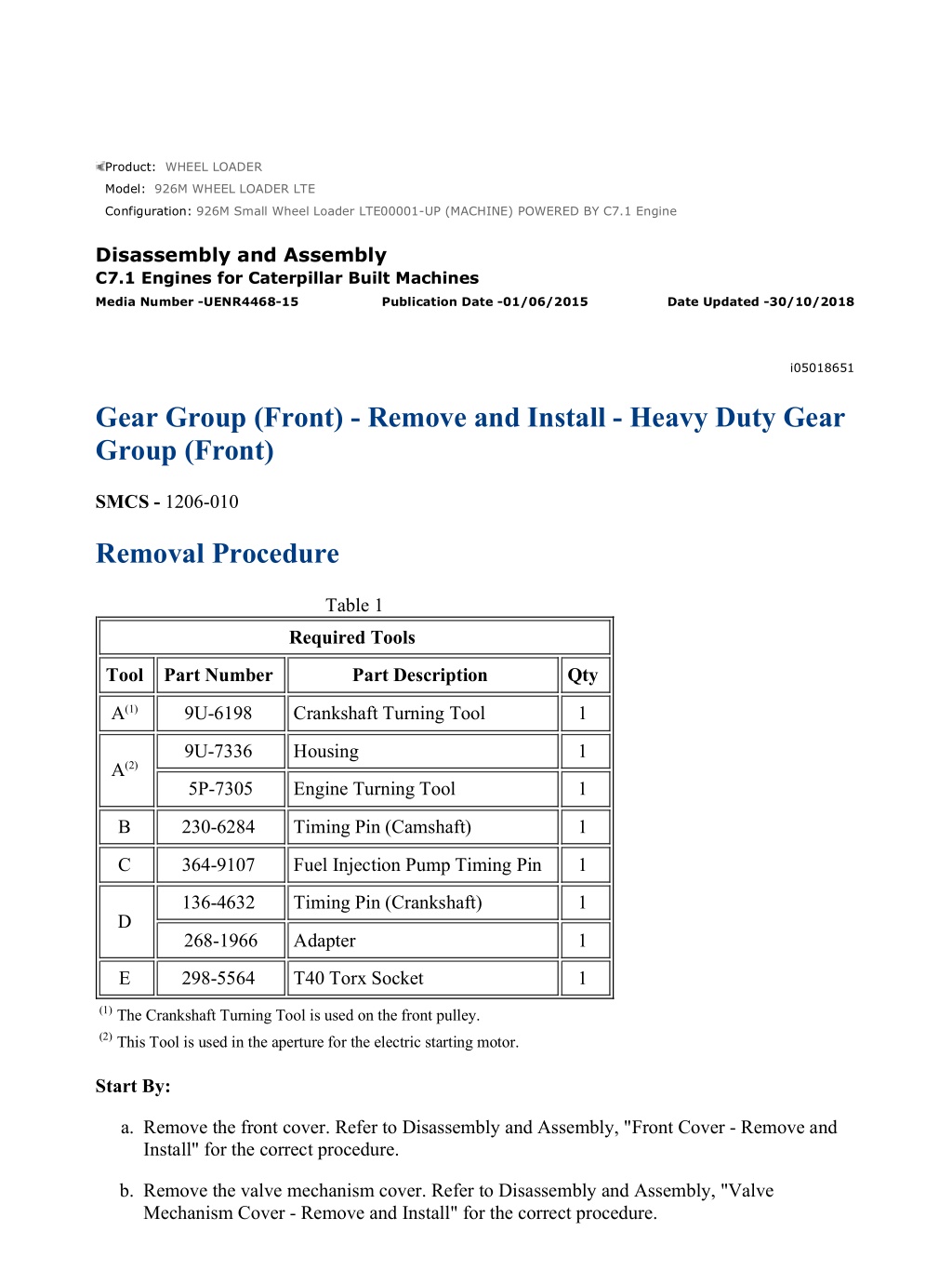
926M Small Wheel Loader LTE00001-UP (MACHINE) POWERED BY C7.1 Engine... 1/21 Product: WHEEL LOADER Model: 926M WHEEL LOADER LTE Configuration: 926M Small Wheel Loader LTE00001-UP (MACHINE) POWERED BY C7.1 Engine Disassembly and Assembly C7.1 Engines for Caterpillar Built Machines Media Number -UENR4468-15 Publication Date -01/06/2015 Date Updated -30/10/2018 i05018651 Gear Group (Front) - Remove and Install - Heavy Duty Gear Group (Front) SMCS - 1206-010 Removal Procedure Table 1 Required Tools Tool Part Number Part Description Qty A(1) 9U-6198 Crankshaft Turning Tool 1 9U-7336 Housing 1 A(2) 5P-7305 Engine Turning Tool 1 B 230-6284 Timing Pin (Camshaft) 1 C 364-9107 Fuel Injection Pump Timing Pin 1 136-4632 Timing Pin (Crankshaft) 1 D 268-1966 Adapter 1 E 298-5564 T40 Torx Socket 1 (1)The Crankshaft Turning Tool is used on the front pulley. (2)This Tool is used in the aperture for the electric starting motor. Start By: a. Remove the front cover. Refer to Disassembly and Assembly, "Front Cover - Remove and Install" for the correct procedure. b. Remove the valve mechanism cover. Refer to Disassembly and Assembly, "Valve Mechanism Cover - Remove and Install" for the correct procedure. https://127.0.0.1/sisweb/sisweb/techdoc/techdoc_print_page.jsp?returnurl=/sis... 2022/5/23
926M Small Wheel Loader LTE00001-UP (MACHINE) POWERED BY C7.1 Engine... 2/21 NOTICE Keep all parts clean from contaminants. Contaminants may cause rapid wear and shortened component life. NOTICE Care must be taken to ensure that fluids are contained during performance of inspection, maintenance, testing, adjusting and repair of the product. Be prepared to collect the fluid with suitable containers before opening any compartment or disassembling any component containing fluids. Dispose of all fluids according to local regulations and mandates. Note: Either Tooling (A) can be used. Use the Tooling that is most suitable. Care must be taken in order to ensure that the fuel injection pump timing is not lost during the removal of the front gear group. Carefully follow the procedure in order to remove the gear group. 1. If the air compressor is equipped with a hydraulic pump, remove the hydraulic pump. Refer to Original Equipment Manufactures (OEM) for the correct procedure. 2. If the engine is equipped, with an air compressor remove the air compressor. Refer to Disassembly and Assembly, "Air Compressor - Remove" for the correct procedure. 3. If the engine is equipped with only a right-hand side hydraulic pump, remove the hydraulic pump. Refer to the OEM for the correct procedure. 4. Use Tooling (A) in order to rotate the crankshaft so that number one piston is at top dead center on the compression stroke. Refer to System Operation, Testing and Adjusting, "Finding Top Center Position for No.1 Piston" for the correct procedure. Note: Do not use excessive force to install Tooling (D). Do not use Tooling (D) to hold the crankshaft during repairs. https://127.0.0.1/sisweb/sisweb/techdoc/techdoc_print_page.jsp?returnurl=/sis... 2022/5/23
926M Small Wheel Loader LTE00001-UP (MACHINE) POWERED BY C7.1 Engine... 3/21 Illustration 1 g02048654 5. Remove plug (2) from the cylinder block. Remove O-ring seal (1) from the plug. 6. Use Tooling (A) in order to rotate the crankshaft so that number one piston is at top dead center on the compression stroke. Refer to System Operation, Testing and Adjusting, "Finding Top Center Position for No.1 Piston" for the correct procedure. Install Tooling (D) through Hole (W) in order to lock the crankshaft. 7. Remove Tooling (D). 8. Use Tooling (A) in order to rotate the crankshaft in a clockwise direction and position the crankshaft at 60 degrees after top dead center. https://127.0.0.1/sisweb/sisweb/techdoc/techdoc_print_page.jsp?returnurl=/sis... 2022/5/23
https://www.ebooklibonline.com Hello dear friend! Thank you very much for reading. Enter the link into your browser. The full manual is available for immediate download. https://www.ebooklibonline.com
926M Small Wheel Loader LTE00001-UP (MACHINE) POWERED BY C7.1 Engine... 4/21 Illustration 2 g03453538 9. Use Tooling (E) in order to loosen threaded inserts (4) on all rocker arms (3). Unscrew threaded inserts (4) on all rocker arms (3) until all valves are fully closed. Note: Ensure that ALL threaded inserts are fully unscrewed. 10. Use Tooling (A) in order to rotate the crankshaft so that number one piston is at top dead center on the compression stroke. Refer to System Operation, Testing and Adjusting, "Finding Top Center Position for No.1 Piston" for the correct procedure. Install Tooling (D) through Hole (W) in order to lock the crankshaft. Refer to Illustration 1. https://127.0.0.1/sisweb/sisweb/techdoc/techdoc_print_page.jsp?returnurl=/sis... 2022/5/23
926M Small Wheel Loader LTE00001-UP (MACHINE) POWERED BY C7.1 Engine... 5/21 Illustration 3 g03453540 11. Install Tooling (B) through Hole (X) in camshaft gear (5) into the front housing. Use Tooling (B) in order to lock the camshaft in the correct position. Refer to System Operation, Testing and Adjusting, "Finding Top Center Position for No.1 Piston" for the correct procedure. 12. Use Tooling (C) in order to lock the fuel injection pump gear in the correct position. Refer to Disassembly and Assembly, "Fuel Injection Pump - Remove" for the correct procedure. Note: The fuel injection pump must remain locked until the procedure instructs you to unlock the fuel injection pump. https://127.0.0.1/sisweb/sisweb/techdoc/techdoc_print_page.jsp?returnurl=/sis... 2022/5/23
926M Small Wheel Loader LTE00001-UP (MACHINE) POWERED BY C7.1 Engine... 6/21 Illustration 4 g03453542 13. If the right-hand side of the engine is equipped, with a hydraulic pump remove the hydraulic pump. Refer to the OEM for the correct procedure. 14. If necessary, remove bolts (6) from plate (7). Remove plate (7) and remove O-ring seal (8). 15. Remove circlip (9) and remove gear assembly (10) from front housing (11). https://127.0.0.1/sisweb/sisweb/techdoc/techdoc_print_page.jsp?returnurl=/sis... 2022/5/23
926M Small Wheel Loader LTE00001-UP (MACHINE) POWERED BY C7.1 Engine... 7/21 Illustration 5 g03453544 16. If necessary, follow Step 16.a through Step 16.b in order to disassemble gear assembly (10). a. Remove circlip (12) from gear (14). b. Place gear assembly (10) on a suitable support. Press bearing (13) from gear (14). https://127.0.0.1/sisweb/sisweb/techdoc/techdoc_print_page.jsp?returnurl=/sis... 2022/5/23
926M Small Wheel Loader LTE00001-UP (MACHINE) POWERED BY C7.1 Engine... 8/21 Illustration 6 g03453546 17. Mark gear (5), gear (15), gear (16), and gear (17) in order to show alignment. Refer to Illustration 6. Note: Identification will ensure that the gears can be installed in the original alignment. 18. Remove camshaft gear (5). Refer to Disassembly and Assembly, "Camshaft Gear - Remove and Install" for the correct procedure. https://127.0.0.1/sisweb/sisweb/techdoc/techdoc_print_page.jsp?returnurl=/sis... 2022/5/23
926M Small Wheel Loader LTE00001-UP (MACHINE) POWERED BY C7.1 Engine... 9/21 Illustration 7 g03453547 19. Remove bolts (21) and bolts (23). 20. Remove tube assembly (22) and the clips from idler gear (15) and idler gear (25). 21. Remove idler gear (25) and idler gear hub (24) from front housing (11). 22. Remove plate (20). 23. Remove idler gear (15) from front housing (11). 24. Remove hub (19) (not shown) from front housing (11). 25. If necessary, remove bearing (18) from front housing (11). Refer to Disassembly and Assembly, "Housing (Front) - Remove" for the correct procedure. Installation Procedure Table 2 Required Tools Tool Part Number Part Description Qty A(1) 9U-6198 Crankshaft Turning Tool 1 A(2) 9U-7336 Housing 1 https://127.0.0.1/sisweb/sisweb/techdoc/techdoc_print_page.jsp?returnurl=/sis... 2022/5/23
926M Small Wheel Loader LTE00001-UP (MACHINE) POWERED BY C7.1 Engi... 10/21 5P-7305 Engine Turning Tool 1 B 230-6284 Timing Pin (Camshaft) 1 C 364-9107 Fuel Injection Pump Timing Pin 1 136-4632 Timing Pin (Crankshaft) 1 D 268-1966 Adapter 1 E 298-5564 T40 Torx Socket 1 7H-1942 Dial Indicator 1 F - Magnetic Base and Stand 1 G 7M-7456 Bearing Mount Compound 1 H 207-1601 Rubber Lubricant 1 (1)The Crankshaft Turning Tool is used on the front pulley. (2)This Tool is used in the aperture for the electric starting motor. NOTICE Keep all parts clean from contaminants. Contaminants may cause rapid wear and shortened component life. Note: The fuel injection pump must remain locked until the procedure instructs you to unlock the fuel injection pump. 1. Ensure that number one piston is at top dead center on the compression stroke. Refer to System Operation, Testing and Adjusting, "Finding Top Center for No. 1 Piston" for the correct procedure. https://127.0.0.1/sisweb/sisweb/techdoc/techdoc_print_page.jsp?returnurl=/sis... 2022/5/23
926M Small Wheel Loader LTE00001-UP (MACHINE) POWERED BY C7.1 Engi... 11/21 Illustration 8 g02048656 2. If necessary, install Tooling (D) into Hole (W) in the cylinder block. Use Tooling (D) in order to lock the crankshaft in the correct position. Refer to System Operation, Testing and Adjusting, "Finding Top Center Position for No.1 Piston". Note: Do not use excessive force to install Tooling (D). Do not use Tooling (D) to hold the crankshaft during repairs. 3. Ensure that all of the components of the front gear group are clean and free from wear and damage. If necessary, replace any components that are worn or damaged. https://127.0.0.1/sisweb/sisweb/techdoc/techdoc_print_page.jsp?returnurl=/sis... 2022/5/23
926M Small Wheel Loader LTE00001-UP (MACHINE) POWERED BY C7.1 Engi... 12/21 Illustration 9 g03453548 https://127.0.0.1/sisweb/sisweb/techdoc/techdoc_print_page.jsp?returnurl=/sis... 2022/5/23
926M Small Wheel Loader LTE00001-UP (MACHINE) POWERED BY C7.1 Engi... 13/21 Illustration 10 g03453629 4. If necessary, install bearing (18) to front housing (11). Refer to Disassembly and Assembly, "Housing (Front) - Install" for the correct procedure. 5. Install hub (19) to the recess of front housing (11). Ensure that oil Hole (Y) is to the top of the hub. 6. Ensure that the fuel injection pump is locked in the correct position. Refer to Disassembly and Assembly, "Fuel Injection Pump - Install". 7. Lubricate idler gear hub (24) with clean engine lubricating oil and install idler gear (25) to the idler gear hub. Install the assembly for idler gear (25) to front housing (11). Note: Ensure that the idler gear hub and the idler gear are correctly aligned. 8. Lubricate idler hub (19) with clean engine lubricating oil. Install idler gear (15) to the idler hub. Ensure that the timing marks are toward the front of the idler gear. Align timing marks on idler gear (15) with gear (17) and gear (16). 9. Position plate (20) onto idler gear (15). Note: Ensure that the identification mark TOP is upward. 10. Position tube assembly (22) and clips onto idler gear (15) and idler gear (25). Install bolts (21) and bolts (23). Note: Ensure that the tube is correctly positioned on the hubs of the idler gears. https://127.0.0.1/sisweb/sisweb/techdoc/techdoc_print_page.jsp?returnurl=/sis... 2022/5/23
926M Small Wheel Loader LTE00001-UP (MACHINE) POWERED BY C7.1 Engi... 14/21 11. Tighten bolts (21) and bolts (23) to a torque of 44 N m (32 lb ft). Illustration 11 g03453549 https://127.0.0.1/sisweb/sisweb/techdoc/techdoc_print_page.jsp?returnurl=/sis... 2022/5/23
926M Small Wheel Loader LTE00001-UP (MACHINE) POWERED BY C7.1 Engi... 15/21 Illustration 12 g03453540 12. Install camshaft gear (5). Loosely install bolt (27) and washer (26) for the camshaft gear. Refer to Disassembly and Assembly, "Camshaft Gear - Remove and Install" for the correct procedure. 13. Install Tooling (B) through Hole (X) in camshaft gear (5) into the front housing. https://127.0.0.1/sisweb/sisweb/techdoc/techdoc_print_page.jsp?returnurl=/sis... 2022/5/23
926M Small Wheel Loader LTE00001-UP (MACHINE) POWERED BY C7.1 Engi... 16/21 Illustration 13 g03453551 Illustration 14 g03453552 14. Ensure that the timing marks on gear (5), gear (15), gear (16), and gear (17) are in alignment. 15. Remove Tooling (B), Tooling (C), and Tooling (D). https://127.0.0.1/sisweb/sisweb/techdoc/techdoc_print_page.jsp?returnurl=/sis... 2022/5/23
926M Small Wheel Loader LTE00001-UP (MACHINE) POWERED BY C7.1 Engi... 17/21 16. When a 8.8 Graded bolt (27) is installed. Tighten the bolt to a torque of 95 N m (70 lb ft). When a 10.9 Graded bolt (27) is installed. Tighten the bolt to a torque of 120 N m (89 lb ft). 17. Use Tooling (F) in order to check the end play of the camshaft gear. Refer to Specifications, "Camshaft" for more information. 18. Use Tooling (F) in order to check the end play of the idler gears. Refer to Specifications, "Gear Group (Front)" and refer to Disassembly and Assembly, "Idler Gear - Remove and Install" for more information. 19. Use Tooling (F) in order to measure the backlash for gear (6), gear (16), gear (17), and gear (18). Refer to Specifications, "Gear Group (Front)" for more information. Illustration 15 g03453676 20. If necessary, follow Step 20.a through Step 20.c in order to assemble gear assembly (10). a. Apply a small continuous bead of Tooling (G) to inner Surface (Z) of bearing (13). Place the inner race of bearing (13) onto a suitable support. Press the shaft of gear (14) onto bearing (13) until the shoulder of the gear is against the bearing. Remove any excess bearing mount compound. b. Install circlip (12) to gear (14). c. Lightly lubricate bearing (13) and gear (14) with clean engine oil. https://127.0.0.1/sisweb/sisweb/techdoc/techdoc_print_page.jsp?returnurl=/sis... 2022/5/23
926M Small Wheel Loader LTE00001-UP (MACHINE) POWERED BY C7.1 Engi... 18/21 Illustration 16 g03453542 21. Install gear assembly (10) to front housing (11). Ensure that the shaft of gear assembly (10) is correctly aligned with the bearing in front housing (11). 22. Install circlip (9) to front housing (11). Note: Ensure that the circlip is correctly located in the front housing. 23. Ensure that there is tactile backlash between the idler gear and the accessory drive gear. 24. If the engine is equipped with only a right-hand side hydraulic pump, install the hydraulic pump. Refer to the OEM for the correct procedure. 25. Lightly lubricate a new O-ring seal (8) with Tooling (H). Install new O-ring seal (8) to plate (7). Install plate (7) to front housing (11). 26. Install bolts (6) to plate (7). Tighten the bolts to a torque of 16 N m (142 lb in). 27. Lubricate each gear with clean engine oil. NOTICE Failure to ensure that the crankshaft is positioned at 60 degrees after top dead center will result in interference between the pistons and the https://127.0.0.1/sisweb/sisweb/techdoc/techdoc_print_page.jsp?returnurl=/sis... 2022/5/23
926M Small Wheel Loader LTE00001-UP (MACHINE) POWERED BY C7.1 Engi... 19/21 valves. Interference between the pistons and the valves will result in damage to the engine. 28. Use Tooling (A) in order to rotate the crankshaft in a clockwise direction and position the crankshaft at 60 degrees after top dead center. Illustration 17 g03453538 29. Use Tooling (E) to tighten threaded inserts (4) on all rocker arms (3). Tighten the threaded inserts to a torque of 30 N m (265 lb in). Note: When the threaded insert is tightened, the threaded insert must be seated correctly into the cup for the pushrod. https://127.0.0.1/sisweb/sisweb/techdoc/techdoc_print_page.jsp?returnurl=/sis... 2022/5/23
926M Small Wheel Loader LTE00001-UP (MACHINE) POWERED BY C7.1 Engi... 20/21 Illustration 18 g02048654 30. Install a new O-ring seal (1) to plug (2). Install the plug into Hole (W) in the cylinder block. Tighten plug (2) to a torque of 21 N m (186 lb in). 31. If the engine is equipped, with an air compressor install the air compressor. Refer to Disassembly and Assembly, "Air Compressor - Install" for the correct procedure. 32. If the air compressor is equipped with a hydraulic pump, install the hydraulic pump. Refer to the OEM for the correct procedure. 33. If the engine is equipped only with a hydraulic pump, install the hydraulic pump. Refer to the OEM for the correct procedure. 34. The engine should not be operated for a period 30 minutes after the threaded inserts on all the rocker arms have been tightened. This period will allow the force from the valve springs to purge off excessive engine oil from the hydraulic lifters. End By: a. Install the front cover. Refer to Disassembly and Assembly, "Front Cover - Remove and Install" for the correct procedure. b. Install the valve mechanism cover. Refer to Disassembly and Assembly, "Valve Mechanism Cover - Remove and Install" for the correct procedure. Mon May 23 08:27:09 UTC+0800 2022 https://127.0.0.1/sisweb/sisweb/techdoc/techdoc_print_page.jsp?returnurl=/sis... 2022/5/23
926M Small Wheel Loader LTE00001-UP (MACHINE) POWERED BY C7.1 Engine... 1/6 Product: WHEEL LOADER Model: 926M WHEEL LOADER LTE Configuration: 926M Small Wheel Loader LTE00001-UP (MACHINE) POWERED BY C7.1 Engine Disassembly and Assembly C7.1 Engines for Caterpillar Built Machines Media Number -UENR4468-15 Publication Date -01/06/2015 Date Updated -30/10/2018 i05018652 Idler Gear - Remove SMCS - 1206-011 Removal Procedure Table 1 Required Tools Tool Part Number Part Description Qty A 364-9107 Fuel Injection Pump Timing Pin 1 B 230-6284 Timing Pin (Camshaft) 1 136-4632 Timing Pin (Crankshaft) 1 C 268-1966 Adapter 1 D 298-5564 T40 Torx Socket 1 Start By: a. Remove the front cover. Refer to Disassembly and Assembly, "Front Cover - Remove and Install" for the correct procedure. b. Remove the valve mechanism cover. Refer to Disassembly and Assembly, "Valve Mechanism Cover - Remove and Install" for the correct procedure. Note: Care must be taken in order to ensure that the fuel injection pump timing is not lost during the removal of the idler gear. Carefully follow the procedure in order to remove the fuel pump gear. NOTICE Keep all parts clean from contaminants. https://127.0.0.1/sisweb/sisweb/techdoc/techdoc_print_page.jsp?returnurl=/sis... 2022/5/23
926M Small Wheel Loader LTE00001-UP (MACHINE) POWERED BY C7.1 Engine... 2/6 Contaminants may cause rapid wear and shortened component life. Illustration 1 g01994555 https://127.0.0.1/sisweb/sisweb/techdoc/techdoc_print_page.jsp?returnurl=/sis... 2022/5/23
926M Small Wheel Loader LTE00001-UP (MACHINE) POWERED BY C7.1 Engine... 3/6 Illustration 2 g01994553 1. Rotate the crankshaft so that number one piston is at top dead center on the compression stroke. Refer to System Operation, Testing and Adjusting, "Finding Top Center Position for No.1 Piston" for the correct procedure. 2. Remove plug (2) from the cylinder block and remove O-ring seal (1) from the plug. 3. Ensure that Tooling (C) is installed in Hole (Y) in the cylinder block. Use Tooling (C) in order to lock the crankshaft in the correct position. 4. Ensure that Tooling (B) is installed into Hole (X) in camshaft gear (3). Use Tooling (B) in order to lock the camshaft in the correct position. Note: Ensure that the gears are marked in order to show alignment. Refer to Illustration 2. 5. Use Tooling (A) in order to lock the fuel injection pump gear in the correct position. Refer to Disassembly and Assembly, "Fuel Injection Pump - Remove" for the correct procedure. https://127.0.0.1/sisweb/sisweb/techdoc/techdoc_print_page.jsp?returnurl=/sis... 2022/5/23
926M Small Wheel Loader LTE00001-UP (MACHINE) POWERED BY C7.1 Engine... 4/6 Illustration 3 g01994556 6. Use Tooling (D) in order to loosen threaded inserts (5) on all rocker arms (6). Unscrew threaded inserts (5) on all rocker arms (6) until all valves are fully closed. Note: Failure to ensure that ALL threaded inserts are fully unscrewed can result in contact between the valves and pistons. https://127.0.0.1/sisweb/sisweb/techdoc/techdoc_print_page.jsp?returnurl=/sis... 2022/5/23
926M Small Wheel Loader LTE00001-UP (MACHINE) POWERED BY C7.1 Engine... 5/6 Illustration 4 g01994576 https://127.0.0.1/sisweb/sisweb/techdoc/techdoc_print_page.jsp?returnurl=/sis... 2022/5/23
926M Small Wheel Loader LTE00001-UP (MACHINE) POWERED BY C7.1 Engine... 6/6 Illustration 5 g01994557 7. Mark plate (8) in order to show orientation. Note: Identification will ensure that the plate can be installed in the original orientation. 8. Remove bolts (7). 9. Remove plate (8). 10. Remove the assembly of idler gear (4). 11. Remove hub (9) from the recess in the front housing. https://127.0.0.1/sisweb/sisweb/techdoc/techdoc_print_page.jsp?returnurl=/sis... 2022/5/23
Suggest: For more complete manuals. Please go to the home page. https://www.ebooklibonline.com If the above button click is invalid. Please download this document first, and then click the above link to download the complete manual. Thank you so much for reading
926M Small Wheel Loader LTE00001-UP (MACHINE) POWERED BY C7.1 Engine... 1/8 Product: WHEEL LOADER Model: 926M WHEEL LOADER LTE Configuration: 926M Small Wheel Loader LTE00001-UP (MACHINE) POWERED BY C7.1 Engine Disassembly and Assembly C7.1 Engines for Caterpillar Built Machines Media Number -UENR4468-15 Publication Date -01/06/2015 Date Updated -30/10/2018 i05018653 Idler Gear - Install SMCS - 1206-012 Installation Procedure Table 1 Required Tools Tool Part Number Part Description Qty A 364-9107 Fuel Injection Pump Timing Pin 1 B 230-6284 Timing Pin (Camshaft) 1 136-4632 Timing Pin (Crankshaft) 1 C 268-1966 Adapter 1 D 298-5564 T40 Torx Socket 1 7H-1942 Dial Indicator 1 E - Magnetic Base and Stand 1 NOTICE Keep all parts clean from contaminants. Contaminants may cause rapid wear and shortened component life. https://127.0.0.1/sisweb/sisweb/techdoc/techdoc_print_page.jsp?returnurl=/sis... 2022/5/23
926M Small Wheel Loader LTE00001-UP (MACHINE) POWERED BY C7.1 Engine... 2/8 Illustration 1 g01996476 https://127.0.0.1/sisweb/sisweb/techdoc/techdoc_print_page.jsp?returnurl=/sis... 2022/5/23
https://www.ebooklibonline.com Hello dear friend! Thank you very much for reading. Enter the link into your browser. The full manual is available for immediate download. https://www.ebooklibonline.com
 POWERED BY")
 POWERED BY")
 POWERED BY")

 POWERED BY")
 POWERED BY")
 POWERED BY")
 POWERED BY")
 POWERED BY")
 POWERED BY")
 POWERED BY")
 POWERED BY")
 POWERED BY")
 POWERED BY")
 POWERED BY")
 POWERED BY")
 POWERED BY")
 POWERED BY")
 POWERED BY")
 POWERED BY")
 POWERED BY")
 POWERED BY")
 POWERED BY")
 POWERED BY")
 POWERED BY")
 POWERED BY")
 POWERED BY")

 POWERED BY")
 POWERED BY")